Now with the 500 ohms cathode resistors and the regulator..been listening for a while and I think the sound is a little darker but detailed,maybe thats a good thing... 🙂
Hello Artosalo (and everyone else sharing),
I really enjoyed your 6P31S amp design, so I modified it to suit what I had around the workshop.
I had a lot of these 6P31S valves lying around so I decided to try to copy your design but to use a single triode for the preamp side rather than the 6N9S double triode (did u just "tie it together" and use it as a regular triode?)
I used a 6S4P (a cheap Russian audio triode) for the first stage.
Here is my schematic.
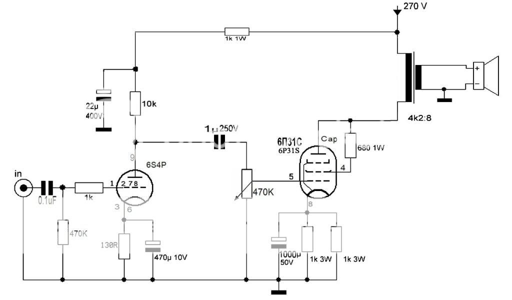
I changed the components around the 6S4P as per a pre-amp circuit I was familiar with so I hope it will be compatible. My tube theory is still kind of rusty as I need help reading tube datasheets to learn which components go with given tubes best.
Thanks in advance.
Feedback is welcome.
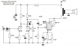
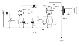
Done. This is the optimum circuit (as per my measurements...):
An externally hosted image should be here but it was not working when we last tested it.
https://www.dropbox.com/s/33njq0opf453kfw/6P31S_6N9S_SE.GIF?dl=0
As an example about the distortion cancelling, when Pout = 3 W, THD at the output is 0,7 %, but at the grid of 6P31S THD is some 2 %.
Sensitivity for 3W out is some 600 mV in.
You have moved the volume potetiometer at the output tube. This means that the voltage amplifier 6S4P has full signal level at it's anode all the time.
My original idea is to have distortion cancelling. This requires that signal levels at the voltage amplifier and output stage are "tied together".
When output power is low, the voltage level at the anode of 1st stage should also be low, etc.
I suppose that now you have low(est) THD at full power, but higher THD at low output.
But if you like your present circuit, just let it be as it is.
You have moved the volume potetiometer at the output tube. This means that the voltage amplifier 6S4P has full signal level at it's anode all the time.
My original idea is to have distortion cancelling. This requires that signal levels at the voltage amplifier and output stage are "tied together".
When output power is low, the voltage level at the anode of 1st stage should also be low, etc.
I suppose that now you have low(est) THD at full power, but higher THD at low output.
But if you like your present circuit, just let it be as it is.
I like it, but could be a bit better. I think I will add some feedback or tone control perhaps. I tried using a 6N2P and doubling the pre-amp input with both sides of the triode but there was too much distortion.
Attachments
You have moved the volume potetiometer at the output tube. This means that the voltage amplifier 6S4P has full signal level at it's anode all the time.
My original idea is to have distortion cancelling. This requires that signal levels at the voltage amplifier and output stage are "tied together".
When output power is low, the voltage level at the anode of 1st stage should also be low, etc.
I suppose that now you have low(est) THD at full power, but higher THD at low output.
But if you like your present circuit, just let it be as it is.
Hi Artosalo,
Whether output power is low or not, the B+ shows a little variation. But the swing is lower at both stages and so is the distortion.
And keeping the first stage working at full power will inject more distortion from the first stage and the sound will be colored more by this stage, which is not necessarily bad, but if I decided to build a 300B amp, I'd like to have a more transparent driver so to listen to the output tube..and the OPT🙂
Last edited:
Hi artosalo, the links are no longer working. Do you mind to post the circuit again? Also, what is the result for 6P13S? Is it better than 6P31S? How do they sound?Done. This is the optimum circuit (as per my measurements...):
An externally hosted image should be here but it was not working when we last tested it.[/URL]
https://www.dropbox.com/s/33njq0opf453kfw/6P31S_6N9S_SE.GIF?dl=0
As an example about the distortion cancelling, when Pout = 3 W, THD at the output is 0,7 %, but at the grid of 6P31S THD is some 2 %.
Sensitivity for 3W out is some 600 mV in.
I just turned on my 6P31S (SE) amp for a listen,and kompared to M2x it has even more bass but the M2x has a "little" more details-but not much.Also, what is the result for 6P13S? Is it better than 6P31S? How do they sound?
You cant belive it only has 3 wats output.I think the (correct me if I´m wrong) 6P13S has lesser Pa.
Member
Joined 2009
Paid Member
The 6P31S is a tube I heard only once, SE too, and I thought it sounded very good indeed. It's not convenient to use top cap so I went in the direction of 2A3 instead but I believe these two tubes can be of comparable sound quality.
The data I have seen indicate 6P13S is easier to drive (with less bias), has higher Pa (14 watt), but slightly higher THD than 6P31S. I have never heard these tubes. I am hoping someone can compare the two in terms of sound in the same triode single ended amp such as artosalo's design.I just turned on my 6P31S (SE) amp for a listen,and kompared to M2x it has even more bass but the M2x has a "little" more details-but not much.
You cant belive it only has 3 wats output.I think the (correct me if I´m wrong) 6P13S has lesser Pa.
- Home
- Amplifiers
- Tubes / Valves
- Question about 6P31S