I have used Crimson CE1704 series vii driving 8ohm speakers for years.how can i use this vi limiter for 2pairs of 2n3773 in 2x30vac transformer?
what are values of resistors to be change? im planning to make a subwoofer amp using apexaudio's subwoofer filter.
I have never had a failure.
The CE1704 are single pair of 2n3773 for the output running on 35+35Vac transformer.
They do have protection built into the PCB.
Series 7 have even more robust protection but Crimson did not recommend them for highest audio quality.
A simple fuse would be adequate protection for your needs.
thanks djk..
I have used Crimson CE1704 series vii driving 8ohm speakers for years.
I have never had a failure.
The CE1704 are single pair of 2n3773 for the output running on 35+35Vac transformer.
They do have protection built into the PCB.
Series 7 have even more robust protection but Crimson did not recommend them for highest audio quality.
andrew thanks, is it ok as djk said with the fuse protection? im planning to make right now for just 2 pairs of 2n3773 but later i'll upgrade for 4 pairs. parts here in our place are difficult to find and if there is its costly. maybe the calculations of apexaudio is ok.
http://www.diyaudio.com/forums/solid-state/167394-quasi-amplifier-beginners-19.html
Limiter activate amp output voltage at clip level (or low if you want limit amp under full power) and it atenuate amp input. Clip level voltage is about 5-15V under rail voltage ( rail voltage +/-75V DC, clip level about 65V).
You can adjust limit level with different value of resistors 820R to get 2V in point 820R, 68R whan amp out is on clip level voltage.
Use formula: Rx=Uclip/0,03 or Uclip=0,03XRx
Rx is 3280R (4x820R) in schematic, Uclip is 100V this clip level is for APEX H900 you must use low value for Rx depend of rail voltage or if you want limit amp at low than full power power use formula P=(UrmsXUrms)/Rload, Urms=Uclip/1,4
Regards
how can i use this vi limiter for 2pairs of 2n3773 in 2x30vac transformer?
what are values of resistors to be change? im planning to make a subwoofer amp using apexaudio's subwoofer filter.
Use PSU with protect from thread: http://www.diyaudio.com/forums/solid-state/162081-dc-servo-mosfet-amplifier-24.html ,
and no need for VI limiter in this case.
I am struggling to find mje150XX transistors here(in logical price),Currently using tip41/42 with lower voltage.I want to know that whether i can use 2sa1943/c5200 combo as drivers for higher voltage rail (i know that these are not driver devices but i am forced to use it because no other high voltage altenative is available).What about using MJE340/350 as drivers also ? Kindly help me because my project is halted for this.
I don't see why not, you were talking about driving lots of outputs for higher power anyway.
Crown uses the 2SA1302/2SC3281 for drivers on some of their bigger amps.
Crown uses the 2SA1302/2SC3281 for drivers on some of their bigger amps.
The original Crown MA5000vz used four MJ15024/25 driven by a pair of MJL1302/3281 per half of the bridge. The 2N3773 was on the same graph of the MJ15024 data sheet for DC current gain.
http://www.crownaudio.com/pdf/legacy/ma5000vz_schematics.zip
(output stage on page 7)
Carver used the 2SA1302/2SC3281 for drivers in several models.
http://www.crownaudio.com/pdf/legacy/ma5000vz_schematics.zip
(output stage on page 7)
Carver used the 2SA1302/2SC3281 for drivers in several models.
Last edited:
hi apex,
I have made two module of this amp.First one made on wrong pcb design(post no.1) with correction done, is working fine but when i made second one on correct pcb design it is not working properly.I am using only 12-0-12 trafo for testing.When i am removing the diodes from the base of bc546,amp works.Voltage drop is also too much when comparing with first module. The positive side of amp is dropping the voltage too much while in first module there is no voltage dropping.MJE 340 getting hot.What may be the problem ? i have checked all the components and tracks for fault and short circuit but unable to find the problem .Is there any mistake with new pcb design ?Kindly suggest me
-regards.
sudhir
hi apex,
I have made two module of this amp.First one made on wrong pcb design(post no.1) with correction done, is working fine but when i made second one on correct pcb design it is not working properly.I am using only 12-0-12 trafo for testing.When i am removing the diodes from the base of bc546,amp works.Voltage drop is also too much when comparing with first module. The positive side of amp is dropping the voltage too much while in first module there is no voltage dropping.MJE 340 getting hot.What may be the problem ? i have checked all the components and tracks for fault and short circuit but unable to find the problem .Is there any mistake with new pcb design ?Kindly suggest me
-regards.
sudhir
No mistake on new pcb, can you post pictures? Use trafo with higher voltage and 60-100W/220V bulb in series with primary for test.
Regards
apexaudio
THis is not a good amp, even for beginners. For a start, there are no emitter resistors in the parallelled transistors (lower half). Many beginners would not know that they would have to match transistors accurately to even have some chance of evening out the power, and even then it is not a good idea to run without emitter resistors.
FOr another, 2N3773's originally (the RCA ones) had fT's of 200 kHz. Not good for audio. Modern ones MAY have fT's around 2 MHz but the data sheets generally say 200kHz still.
470 pF compensation capacitors will cause slew rate limiting at 4 MV/s - really poor. The best I can say is that this might match the slow speed of 2N3773's.
As for the output power and current, high current/voltage applications are not really beginners' projects. I'm not convinced that you could in fact obtain 550W from just four (x2) 2N3773's anyway. At least not driving difficult loads. Maybe just resistors.
Something like the Maplin 100W amp (two 2N3055/MJ2955 pairs) running from up to 40V is much more suitable. In fact that circuit was not so different, but the compensation capacitors were smaller (because the 2N3055 is faster).
ANd would beginners have 500W or more speaker capability?
apexaudio
THis is not a good amp, even for beginners. For a start, there are no emitter resistors in the parallelled transistors (lower half). Many beginners would not know that they would have to match transistors accurately to even have some chance of evening out the power, and even then it is not a good idea to run without emitter resistors.
FOr another, 2N3773's originally (the RCA ones) had fT's of 200 kHz. Not good for audio. Modern ones MAY have fT's around 2 MHz but the data sheets generally say 200kHz still.
470 pF compensation capacitors will cause slew rate limiting at 4 MV/s - really poor. The best I can say is that this might match the slow speed of 2N3773's.
As for the output power and current, high current/voltage applications are not really beginners' projects. I'm not convinced that you could in fact obtain 550W from just four (x2) 2N3773's anyway. At least not driving difficult loads. Maybe just resistors.
Something like the Maplin 100W amp (two 2N3055/MJ2955 pairs) running from up to 40V is much more suitable. In fact that circuit was not so different, but the compensation capacitors were smaller (because the 2N3055 is faster).
ANd would beginners have 500W or more speaker capability?
In real world this overcompensate circuit without any adjust is still valuable, look at the posts #182 and #243.
Any of my amp is good for beginners with single side pcb and without smd parts...
Now its working.I dont know what was the fault, i just changed the mje340/350(according to multimeter testing these are ok).i am attaching the pictures of both modules.one is made on reversed printed pcb.I have ordered for a 50-0-50 trafo & it will be used with 5pairs of o/p,20000uf cap per side.No mistake on new pcb, can you post pictures? Use trafo with higher voltage and 60-100W/220V bulb in series with primary for test.
Regards
just one question more...........is it a stable amp ? because i have read many critisism of this amp in this forum but i have selected this amp because of its simplicity & power.(offcourse i have a lot of 2n3773s too)
photo in next post.
Last edited:
How big is the 50-0-50 ?
If it's big (800VA) it might have as good as 4% regulation, so if the line voltage does not rise at all you will have about ±73V at idle. If the line rises you might have a problem.
http://www.antekinc.com/pdf/AN-8450.pdf
Can you select your devices for forward biased breakdown voltage?
I would buy an 800VA 45-0-45, the no-load voltage with 5% high line would be around ±69V.
http://www.antekinc.com/pdf/AN-8445.pdf
The difference between 50V and 45V is less than 1dB.
Last edited:
to djk,
i am getting it manufactured from a local winder.According to my specification he will wind it for 50-0-50, 15amp.i will post the measurements after delivery.
i am getting it manufactured from a local winder.According to my specification he will wind it for 50-0-50, 15amp.i will post the measurements after delivery.
All transformers are rated at full load with nominal line voltage.
Have him wind it for 45-0-45 unless you can select transistors as I described.
Have him wind it for 45-0-45 unless you can select transistors as I described.
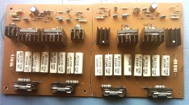
Now its working.I dont know what was the fault, i just changed the mje340/350(according to multimeter testing these are ok).i am attaching the pictures of both modules.one is made on reversed printed pcb.I have ordered for a 50-0-50 trafo & it will be used with 5pairs of o/p,20000uf cap per side.
just one question more...........is it a stable amp ? because i have read many critisism of this amp in this forum but i have selected this amp because of its simplicity & power.(offcourse i have a lot of 2n3773s too)
photo in next post.
Amp is very stable, becouse it's overcompensate for working in class B without audiable distortion. Critisism is from people who are not diyers, just like teoretical discus about amps, and this is practical amp, clone of old DYNACORD, amp was usen for powered mixers and guitar amps.
Regards
- Home
- Amplifiers
- Solid State
- QUASI Amplifier for Beginners