Hello Mr APEX, i have many transistors PNP. What can be able modfication from emitor follower to colector fllwr this final.....???
hello sir ...
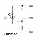
pls tel me how can i add clip led in my amp..??
Use this circuit
Attachments
Hello Mr APEX, i have many transistors PNP. What can be able modfication from emitor follower to colector fllwr this final.....???
Do You want QUASI PNP output stage?
thanks for the amplifier schematics🙂 . i am new to building amps.i have some queries
1 what are the rail voltages for driving 2 ohm load & using 4 pairs of o/p transistors per channel.what else i have to change.( i will be bridging two such channels to drive 4 ohm load ).
2. what will be resulting power in bridge mode when driving 4 ohm load
plz look at this link
http://www.electronica-pt.com/circuitos/en/audio-amplifiers/44-audio-amplifier-90-100w-with-2n3773.html
3. is the above ckt class b or class ab?
4. what is the differnce in qualitywise between the above design & ur design
plz dont be offended i am only a mechanical engineer 😱
please reply to all my queries 🙁
. i am new to building amps.i have some queries1 what are the rail voltages for driving 2 ohm load & using 4 pairs of o/p transistors per channel.what else i have to change.( i will be bridging two such channels to drive 4 ohm load ).
2. what will be resulting power in bridge mode when driving 4 ohm load
plz look at this link
http://www.electronica-pt.com/circuitos/en/audio-amplifiers/44-audio-amplifier-90-100w-with-2n3773.html
3. is the above ckt class b or class ab?
4. what is the differnce in qualitywise between the above design & ur design
plz dont be offended i am only a mechanical engineer 😱
please reply to all my queries 🙁
The schematic that you mentioned, I did it and it goes out into smoke. I check and recheck with the schematic and the PCB layout, but is just didn't work. Try it for yourself! maybe you could get it right!
Best regard
Albert
Best regard
Albert
I am now in the process of the making of the amplifier that shown in post #1. I'll post the result soon.
Albert
Albert


I don't think the BD139/140 are rated at high enough voltage to work at ±65V, nor are the TIP 41C/42C.
mje15032/33=TIP???
for +-75 to 80v any substitute for mje15032/33?
I don't think the BD139/140 are rated at high enough voltage to work at ±65V, nor are the TIP 41C/42C.
for +-75 to 80v any substitute for mje15032/33?
"for +-75 to 80v any substitute for mje15032/33? "
That's a pretty good part, and it shouldn't be too hard to find.
The NJW 0281/0302 would make a good substitute. The ON Semi price reference is $0.93 vs $0.61 for the MJE 15032/33.
http://www.onsemi.com/pub_link/Collateral/NJW0281-D.PDF
That's a pretty good part, and it shouldn't be too hard to find.
The NJW 0281/0302 would make a good substitute. The ON Semi price reference is $0.93 vs $0.61 for the MJE 15032/33.
http://www.onsemi.com/pub_link/Collateral/NJW0281-D.PDF
post228 will not be reliable with +-65Vdc.
Most of the transistors are the wrong type or wrong voltage rating.
The maximum voltage I would recommend is +-40Vdc.
Most of the transistors are the wrong type or wrong voltage rating.
The maximum voltage I would recommend is +-40Vdc.
I don't think the BD139/140 are rated at high enough voltage to work at ±65V, nor are the TIP 41C/42C.
Yes, but with MJEs will work at +/-65V, only I suggest 2N5551 instead BC546.
Yap! you're right. it is 40V to be precise. Thanks for correcting.I don't think the BD139/140 are rated at high enough voltage to work at ±65V, nor are the TIP 41C/42C.
Best regard
"MJE350 are not the correct type for VAS duty. "
Sure, there are better types. Consider that it speeds up to 60Mhz around 20mA (use a heatsink), it may be adequate for this type of amplifier.
Sure, there are better types. Consider that it speeds up to 60Mhz around 20mA (use a heatsink), it may be adequate for this type of amplifier.
driver
what do you think is the suitable driver for this amp on this site???
Crown - The Professional Choice
any suggestions?
what do you think is the suitable driver for this amp on this site???
Crown - The Professional Choice
any suggestions?
pnp output
care to share your quasi pnp output.
thanks🙂🙂
Do You want QUASI PNP output stage?
care to share your quasi pnp output.
thanks🙂🙂
care to share your quasi pnp output.
thanks🙂🙂
You can use same circuit for quasi pnp output, just replace all pnp transistors with npn and all npn replace with pnp, revert diode polarity and use revert +/- rail voltage polarity and you get quasi pnp amp.
- Home
- Amplifiers
- Solid State
- QUASI Amplifier for Beginners