hi
hell sir
i use schematic .....
thanx....
A square/Jon, which one did you use; the schematic or the PCB? Judging on your QUASI 550W Amplifier project, it seem that you follow the schematic.
hell sir
i use schematic .....
thanx....
This design should be ideal for a subwoofer amplifier, assuming it doesent chicken out below 50Hz.
Apex, can i use 2sc5200 for the drivers?, i have 10 pcs of these..
You can use 2SC5200 as outputs.
Regards
bridging
apex sir...,
i'd like to ask something...
how do i bridge amps like this without using an inverter or birdge buffer???...
tnx and regards...
ees...
apex sir...,
i'd like to ask something...
how do i bridge amps like this without using an inverter or birdge buffer???...
tnx and regards...
ees...
apex sir...,
i'd like to ask something...
how do i bridge amps like this without using an inverter or birdge buffer???...
tnx and regards...
ees...
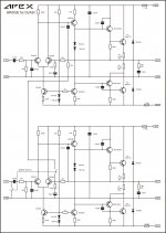
Yes, use this schematic for simple bridge.
Regards
Attachments
Yes, use this schematic for simple bridge.
Regards
thank you sir...
i see...a 22k resistor connects the two amps...
ahmmm...what is the idea behind???...
so i can implement it in any other amps that i may encounter...
please help...
tnx and regards...
ees...
22k at the input is to match the 22k in the NFB.
is it necessary to match the input and the feedback resistors???...why???...
so if i have 33k feedback i'd also use the same value at hte input to bridge the amp...
thanks...
ees
input bias currents
yes, it is very important.
Any schematic that shows different values should explain why it can be considered as a very rare exception.
yes, it is very important.
Any schematic that shows different values should explain why it can be considered as a very rare exception.
yes, it is very important.
Any schematic that shows different values should explain why it can be considered as a very rare exception.
ok thank you sir...
one more thing...
since i've been asking about bridging,
i'd like to know how grounded bridge topology differ from bridge tied load...
i ask this because somebody told me that his amp uses the said topology...
and i am very sorry i dont have the schema...
thanks...
ees
Attachments
thank you sir...
i see...a 22k resistor connects the two amps...
ahmmm...what is the idea behind???...
so i can implement it in any other amps that i may encounter...
please help...
tnx and regards...
ees...
Simple, output of first amp is connect to inverting input of second.
![SDC10133 [1024x768].JPG](/community/data/attachments/188/188590-0d0280bcc63ba3f2320516a41c9c12ba.jpg?hash=DQKAvMY7o_)
![SDC10134 [1024x768].JPG](/community/data/attachments/188/188600-858df453c4d9961a28881715139084e5.jpg?hash=hY30U8TZlh)
![SDC10135 [1024x768].JPG](/community/data/attachments/188/188606-ebd6a2a44e4183243df7bc3547a2772f.jpg?hash=69aipE5Bgy)
![SDC10139 [1024x768].JPG](/community/data/attachments/188/188640-fa40b9a1ae5c5d7ea47bf8bf675f2647.jpg?hash=-kC5oa5cXX)
![SDC10138 [1024x768].JPG](/community/data/attachments/188/188633-0ac1e6751bf3135d9dc195544c362a58.jpg?hash=CsHmdRvzE1)
![SDC10137 [1024x768].JPG](/community/data/attachments/188/188630-51b80bb6a9d15b4923d77d8de165de67.jpg?hash=UbgLtqnRW0)
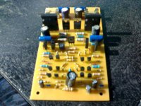
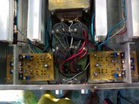
Nice PCB with TO3 outputs on it, but can be smaler or you can add protect circuit.
What is 'standard preamp'?
Regards
What is 'standard preamp'?
Regards
hi
hello sir nice work.....
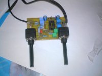
And Apex ML3 tone control with STANDARD preamp...
hello sir nice work.....
i have a question is this the right value of 100n= 0.1/100 mylar/ 104 ceramic and
470=.00047/100 mylar/ 471 ceramic?
can you give a limiter circuit for this amp.
470=.00047/100 mylar/ 471 ceramic?
can you give a limiter circuit for this amp.
i have a question is this the right value of 100n= 0.1/100 mylar/ 104 ceramic and
470=.00047/100 mylar/ 471 ceramic?
can you give a limiter circuit for this amp.
For limiter see posts #179 and #181.
Regards

Standard preamplifier is the name of Borivoje Jagodic stereo preamp.
This is schematic and PCB of it.
Regards
I prefer dual pots for stereo preamp, see thread http://www.diyaudio.com/forums/solid-state/167363-mic-line-eq-preamps-4.html post #39.
Regards
Attachments
- Home
- Amplifiers
- Solid State
- QUASI Amplifier for Beginners