thx Mr. Miles for this quasi amp
if you teach me sir how to do a PNP quasi i will update sooner or later i'm glad that we have you Mr. Miles thank you very much.
regards
@apex yes sir miles do i have to reverse polarity the diodes and the zener diodes and the pre drivers and vas from pnp to npn and vice versa of their location from mje340=mje350 mje150031=mje150030 location
If you want PNP outputs, you must revert rail polarity, diodes polarity and all transistors must be pnp instead npn and vice versa.
pnp quasi
sir miles kindly check if it is correct
If you want PNP outputs, you must revert rail polarity, diodes polarity and all transistors must be pnp instead npn and vice versa.
sir miles kindly check if it is correct
not correct.
you have used the PSU Zero Volts (between the capacitors) as an Audio Ground. no no.
you have swapped the +ve & -ve supplies.
you have no emitter resistors in the emitter leads of the four leftmost output devices. no no.
you have the mains fuse and the mains switch in the two different Mains Lines. no no.
Last edited:
Wrong!?
Hi people!
Where the schematics of this quasi amplifier, as one friend told me that she is wrong? 😕
Cheers!
Hi people!
Where the schematics of this quasi amplifier, as one friend told me that she is wrong? 😕
Cheers!
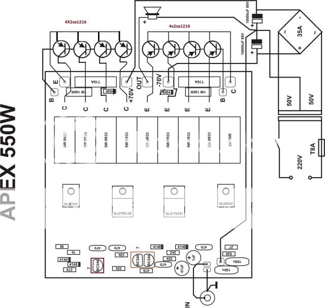
resistor of 0,33ohm/5W!
Need to add a resistor of 0.33ohm/5W on the transistor 2N3773 or 2SC2922 (for Ucc=+/-70V) in the emitter of the negative branch of power supply.
Ceers😉!
Hipost number 1 page 1
Need to add a resistor of 0.33ohm/5W on the transistor 2N3773 or 2SC2922 (for Ucc=+/-70V) in the emitter of the negative branch of power supply.
Ceers😉!
Last edited:
APEX at 2 OHM ??
Hi there
i want to use apex550 @ 2 ohm.
what should be the optimum rail voltage.i mean i want
400 watts @ 2 ohm
800 watts @ 4 ohm (bridged) mono
is it possible? thanks in advance 🙂
Hi there
i want to use apex550 @ 2 ohm.
what should be the optimum rail voltage.i mean i want
400 watts @ 2 ohm
800 watts @ 4 ohm (bridged) mono
is it possible? thanks in advance 🙂
400W into 2r0 is equivalent to 40Vpk and 10Apk into your 2r0 load.
Expect +-50Vdc to be suitable.
Two amplifiers from the same PSU will require ~60Apk transient current demand.
Design for that 60Apk, or you won't get decent performance from the speakers.
Expect +-50Vdc to be suitable.
Two amplifiers from the same PSU will require ~60Apk transient current demand.
Design for that 60Apk, or you won't get decent performance from the speakers.
So i can use the apex550 at +-50 rail voltage at 2 ohm load without any changes in design.(i will upgrade power transformer & capacitor for more current)
transformer will be 36-0-36 volt secondary
what should be secondary current rating of transformer for one mono bridged channel(total audio power will be 800 watt) how did you calculate 60Apk
what should be appropriate filter cap size
thanks AndrewT 🙂
transformer will be 36-0-36 volt secondary
what should be secondary current rating of transformer for one mono bridged channel(total audio power will be 800 watt) how did you calculate 60Apk
what should be appropriate filter cap size
thanks AndrewT 🙂
I recommend twice the VA rating on the transformer as you expect watts out, say 1.5KVA for your amplifier. You could get by with a fraction of that but would have to raise the voltage and it could overheat with large duty-cycle signals.
I like the quasi type circuit . It has a good bass response. Our vintage audio amplifier 1979 AKAI AA-1115 uses a Quasi type output. it uses rubycon capapitors, 4 NPN 2SD313 output transistor. Presently this amplifier still sounds good.
Last edited:
Stucked again
hi guys
i have some queries
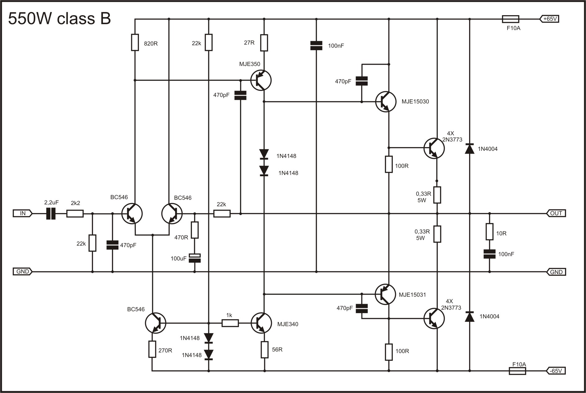
1) In the scematic there are 2 capacitors 2.2 uf & 100 uf
http://www.diyaudio.com/forums/atta...uasi-amplifier-beginners-apex-550w-classb.jpg
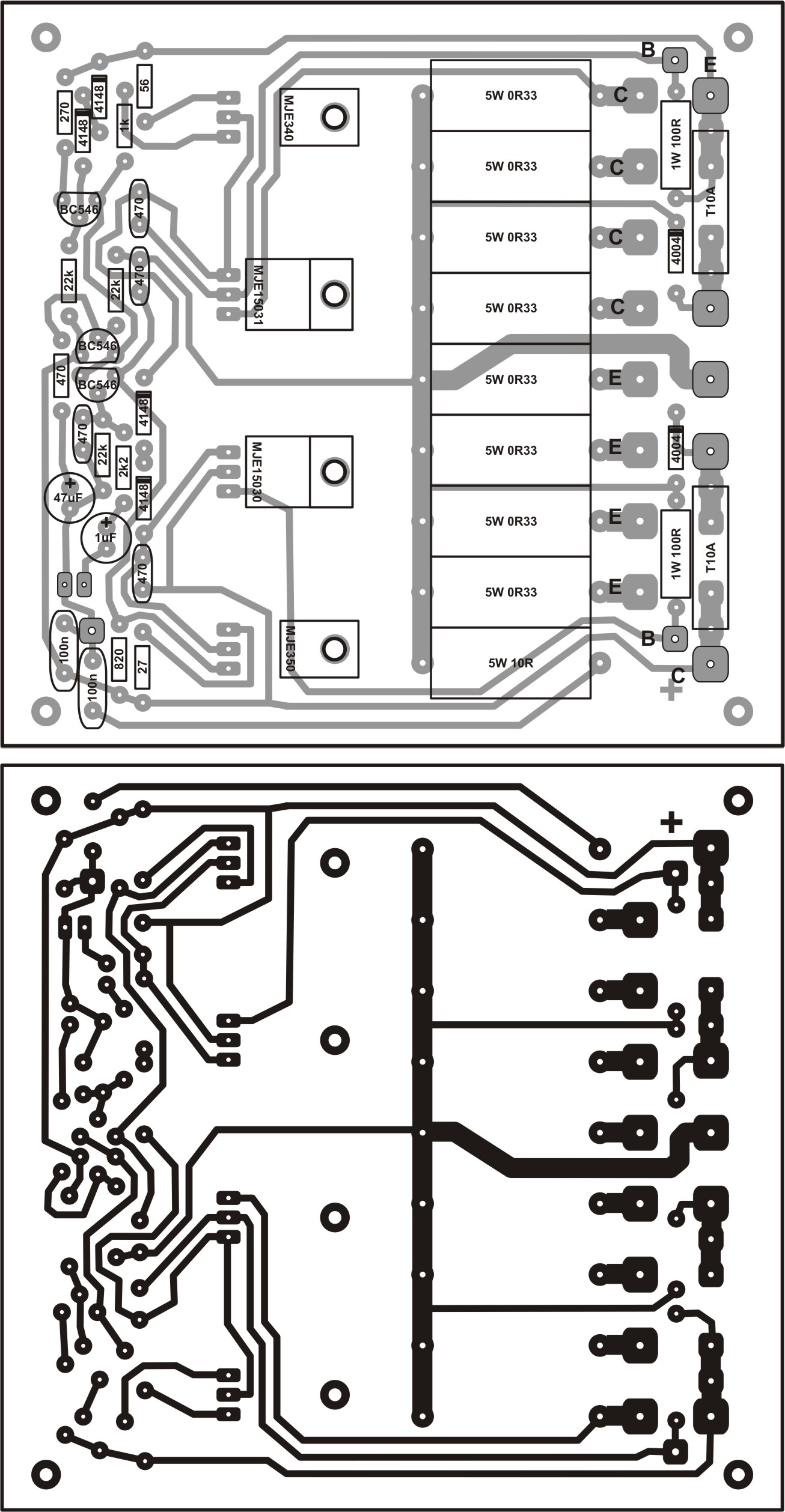
But in layout they are shown as 1 uf & 47 uf respectively
http://www.diyaudio.com/forums/atta...amplifier-beginners-apex-550w-class-b-pcb.jpg 😕
which one is correct?
2) In scematics emitter of mje15031 is directly connected to speaker output
But in layout it is connected with 0.33R 5W resistor in between.
which one is correct & why ,because i have seen this in other designs also.
3) What is the wattage of resistors which are not mentioned?
thanks
i should have chosen electronics as my subject
hi guys
i have some queries
1) In the scematic there are 2 capacitors 2.2 uf & 100 uf
http://www.diyaudio.com/forums/atta...uasi-amplifier-beginners-apex-550w-classb.jpg
But in layout they are shown as 1 uf & 47 uf respectively
http://www.diyaudio.com/forums/atta...amplifier-beginners-apex-550w-class-b-pcb.jpg 😕
which one is correct?
2) In scematics emitter of mje15031 is directly connected to speaker output
But in layout it is connected with 0.33R 5W resistor in between.
which one is correct & why ,because i have seen this in other designs also.
3) What is the wattage of resistors which are not mentioned?
thanks
i should have chosen electronics as my subject
Schematic is not correct!!??
Hi Sanju21!
Note: The schematic under point 1) has a bug, or is not correct!?😕😀
Cheers!
Hi Sanju21!
Note: The schematic under point 1) has a bug, or is not correct!?😕😀
Cheers!
Last edited:
Such should be (see Figure 1)!😉🙂
Best regards!
Best regards!
Attachments
Last edited:
Hi ,
I have 2SK1518 about 30pcs. in all, found it from ac servo driver pack of robotic machine.
Can this be use as output stage on this power amplifier?
please advice,
regards....
I have 2SK1518 about 30pcs. in all, found it from ac servo driver pack of robotic machine.
Can this be use as output stage on this power amplifier?
please advice,
regards....
Hello!Hi ,
I have 2SK1518 about 30pcs. in all, found it from ac servo driver pack of robotic machine.
Can this be use as output stage on this power amplifier?
please advice,
regards....
According to the features you MJ15003 transistors with 2sk1518, if so - fit!?
cheers!😉
Last edited:
thank for reply formula 22,Such should be (see Figure 1)!😉🙂
Best regards!
i am unsure of adding a 100R & 0.22R resistor.
as i have assembled the circuit (point to point hardwired without pcb) & ran the amplifier on rail voltage 40 vdc & it sounded great without any problem.
now i want to use pcb but it's layout differs from the circuit given (which i mentioned in my post #594.
SIR, i am not questioning your knowledge,it's just that i am noob & doesnot understand the logic.
& does anyone has links for correct pcb diagram.
SORRY formula 22 if anything i said offended you
Such should be (see Figure 1)!😉🙂
Best regards!
thank for reply formula 22,
i am unsure of adding a 100R & 0.22R resistor.
as i have assembled the circuit (point to point hardwired without pcb) & ran the amplifier on rail voltage 40 vdc & it sounded great without any problem.
now i want to use pcb but it's layout differs from the circuit given (which i mentioned in my post #594).
SIR, i am not questioning your knowledge,it's just that i am noob & doesnot understand the logic.
& does anyone has links for correct pcb diagram.
SORRY formula 22 if anything i said offended you
- Home
- Amplifiers
- Solid State
- QUASI Amplifier for Beginners