Neither ONsemi, nor Fairchild quote fT data in the MJE340 device datasheet.
Where did 15MHz to 60MHz come from?
Where did 15MHz to 60MHz come from?
Neither ONsemi, nor Fairchild quote fT data in the MJE340 device datasheet.
Where did 15MHz to 60MHz come from?
Same Qs rings in my mind also..........
ouch that's what we call respect to others or senior members btw so it is ok to use tip's or not sir
yes. coz the title "sir" are only given to knight's..Don't call me "sir" I am not entitled to that.
god day and regards.
"Neither ONsemi, nor Fairchild quote fT data in the MJE340 device datasheet.
Where did 15MHz to 60MHz come from? "
From National Semiconductor data for their raw die, they published a fT vs current graph. The highest speed came at a higher current than what the Vas would be comfortable with on high voltage rails. One could parallel them as I have seen in some designs.
"it possible to use tips or not "
The TIP 'C's are 100V parts, so the max voltage you can run must be no more than ±50V. TIP 'F's are 160V (if you can find them). However, they are only 3Mhz and you would probably need to change the frequency compensation of the amplifier.
Sir is a title of respect, and no one deserves it from the circumstance of birth (titles of nobility). People I work with and have earned my respect always receive a 'thank you sir' from me at work when they have done something for me.
Last edited:
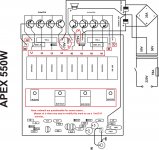
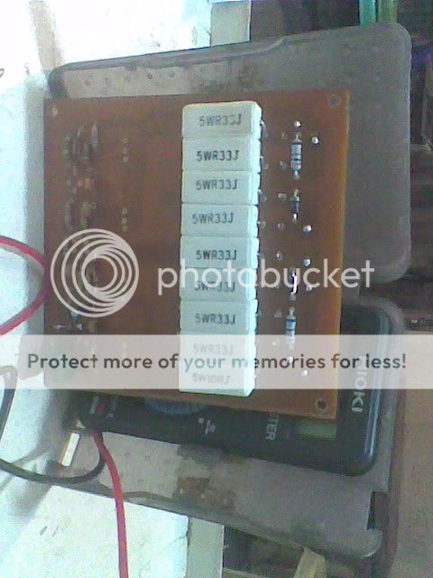
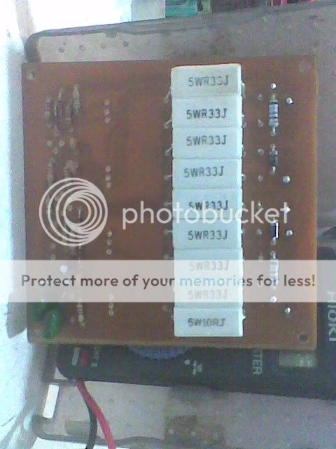
@apex sir i probably salute you and more power the big thing is my 550 watt P.A. kicks the 2x18 800watts only using tip41c and 42c and it kicks whooaaaa i'm very proud of you sir
Regards
Regards
@apex sir i probably salute you and more power the big thing is my 550 watt P.A. kicks the 2x18 800watts only using tip41c and 42c and it kicks whooaaaa i'm very proud of you sir
Regards
Good news, can you post pictures of final amp?
Regards
"Neither ONsemi, nor Fairchild quote fT data in the MJE340 device datasheet.
Where did 15MHz to 60MHz come from? "
From National Semiconductor data for their raw die, they published a fT vs current graph. The highest speed came at a higher current than what the Vas would be comfortable with on high voltage rails. One could parallel them as I have seen in some designs.
"it possible to use tips or not "
The TIP 'C's are 100V parts, so the max voltage you can run must be no more than ±50V. TIP 'F's are 160V (if you can find them). However, they are only 3Mhz and you would probably need to change the frequency compensation of the amplifier.
Sir is a title of respect, and no one deserves it from the circumstance of birth (titles of nobility). People I work with and have earned my respect always receive a 'thank you sir' from me at work when they have done something for me.
Can you share this datasheet from National for the MJE's I'm really interested. I found one datasheet from National but there were no info of this kind.
Thanks!
MJE340 FT=10Mhz
Here it is: 😉
It was from a very old data book, I'm not sure it is still around, but I will look.
Here it is: 😉
Attachments
Here it is: 😉
Thanks!
It contains more detailed info for MJE340 but there is no fT vs current graph. 🙁
So if someone have is please post.
LED VU
sir apex i like to put this in my h900 do you have pcb layout of this?
Good news, can you post pictures of final amp?
Regards
I will sir as of now I'm into a second board for etching he he he i got to use the old good way for making the PCB wish me good luck sir
regards
So what are the benefits of circuit 2 over circuit 1?? Secondly, why is the low value resistor,on the bottom most output transistor, in the collector leg and not in the emitter??
@apex sir is it possible to use a PNP trannie to this P.A. and how pls enlighten me sir and i ask something else else is the feedback resistor of this AMP is 22k or 2.2k where can i find it the quality is good but to much med or i mean to much vocals what value of resistor di i change to become lesser meds/vocals
regards...
regards...
Attachments

- Home
- Amplifiers
- Solid State
- QUASI Amplifier for Beginners