quazar amplifier
Hi andrewlebon,
Please send me pcb,schematic and pictuers of your full project.
My email ID: redhorseaudio@yahoo.com
Hi andrewlebon,
Please send me pcb,schematic and pictuers of your full project.
My email ID: redhorseaudio@yahoo.com
@ASIA
Hi friend!
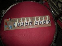
It is clearly stated on my site just above that picture: "QUASOR done by Mr. Pranay Kundu from Indonesia on PCB-s designed by Mr. Radan Malbasic."
So, you decided not to work with my PCB and layout but with solution from other people. You will have to address them for clarifications. Picture has been included jut to show how other builders solve PCB on their own.
My PCB and layout are given freely on my site under
RASPORED DELOVA = layout (in GIF format)
PLOCICA = PCB (in Adobe PDF format)
Hi friend!
It is clearly stated on my site just above that picture: "QUASOR done by Mr. Pranay Kundu from Indonesia on PCB-s designed by Mr. Radan Malbasic."
So, you decided not to work with my PCB and layout but with solution from other people. You will have to address them for clarifications. Picture has been included jut to show how other builders solve PCB on their own.
My PCB and layout are given freely on my site under
RASPORED DELOVA = layout (in GIF format)
PLOCICA = PCB (in Adobe PDF format)
sir,
with respect to you as a designer,i am very sorry the language on site is foreign to me,sorry.
but still manage to download pcb and landscape which is i believe from you
i have a question sir upon using other irf device i do know irfp240 is your choice,what are the other irf ranges we can use?
with respect to you as a designer,i am very sorry the language on site is foreign to me,sorry.
but still manage to download pcb and landscape which is i believe from you
i have a question sir upon using other irf device i do know irfp240 is your choice,what are the other irf ranges we can use?
Attachments
I just recently build this power amp. I used 2SC5200 and 2SA1943 as driver all other transistors are on specs but gives me distorted sound at high volume about 2 amps at 28v output. I donot have MJ15034/35 available.
My power supply is 60,000uf per rail at 93vdc 28amp rated EI transformer. Can somebody give me tips to make my amp drive as specified by Sir Bora?
Thank you.
My power supply is 60,000uf per rail at 93vdc 28amp rated EI transformer. Can somebody give me tips to make my amp drive as specified by Sir Bora?
Thank you.
Andrew,
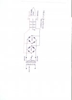
I used the PCB design by Dr. Borina Amaterska Svastara. So that the two positive cables are soldered in the cap bank PCB and same with the negative cables. All ground cables are soldered to PSU ground.
Would like advise if this PSU work to the power amp requirement. Sorry for the bad scanned drawing. Thanks.🙂
Attachments
Dear all,
The amplifier is working good now, clear and very strong. I added 2 more pair of cap at PSU total now is 100,000uf per rail. In addition, I installed 6amps 1000 volts diodes at the output to rails in reverse polarity to avoid loading the amp from speaker.
The amplifier is working good now, clear and very strong. I added 2 more pair of cap at PSU total now is 100,000uf per rail. In addition, I installed 6amps 1000 volts diodes at the output to rails in reverse polarity to avoid loading the amp from speaker.
Dear all,
The amplifier is working good now, clear and very strong. I added 2 more pair of cap at PSU total now is 100,000uf per rail. In addition, I installed 6amps 1000 volts diodes at the output to rails in reverse polarity to avoid loading the amp from speaker.
Hi Joselito,
Nice project, appreciate if you could post pictures of your work.
Question, are all of this parts locally available in Raon Manila?
Planning also to have this circuit one of this days.
regards
Hello AN214Q,
All parts are available in Raon, Manila except the driver MJE15034/35. I had replaced them with 2SC5200/2SA1943. I could not take pics right now need to disassemble it from the rack and it is being used in mobile now. I will share the pics once have it back.
I'm planning to replace the output with IRFP460 but having trouble locating good quality mosfets here in Cdo City.
Rgds
AN214Q,
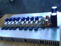
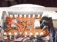
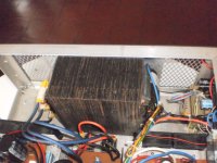
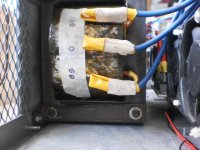
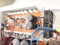
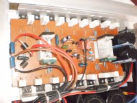
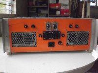
Here are some old pics of the amp prior initial testing. As you can see the caps with only 2 pairs, I had to R&R them with 5 pairs slim type to fit properly in the location(100,000uf per rail). Also the wires are not yet arranged. The whole assembly mass is 38 kgs.
The finished amp can put out 1000 watts in 4ohm load clear sound at normal operating temperature. Thanks to the designer Dr. Bora for sharing this piece of wisdom to us.
rgds
Attachments
joselito,
sir bora noted not to use irfp460 to me because of parasitic oscillation issue,what fets you use?
how do you implement the diode is this right?
pls see attachment
sir bora noted not to use irfp460 to me because of parasitic oscillation issue,what fets you use?
how do you implement the diode is this right?
pls see attachment
Attachments
Last edited:
- Status
- Not open for further replies.
- Home
- Amplifiers
- Solid State
- quasar amplifier by dr bora 1000 watt