QUASAR Mosfet dumpers / slew rate
For my project, active speakers utilizing Manger speakers, I have been considering a Quad 405 "reborn", too.
However Manger recommends a slew rate of 100 Volts per microsecond.
With 3 Mosfets paralleled on each rail the gate/ source capacity
charge/discharge current is about 300mA for 100 Volts/ microsecond and this rough calculation does not even consider the non linear behavior of the input capacity in the proximity of gate threshold. It is an approximation as the non linear differential equation is not solvable only approximately.
So I assume unfortunately the QUASAR design will not match the slew rate requirement.
hahfran,
Slew rate is limited by amplifier power bandwidth - in this case is ~ 120Khz.
To get 100V/us is difficult even with bipolars, who - by the way -suffer from same large parasitic output capacitance as MOS-FET's.
Anyhow those parasitic capacitances will significantly decrease by increasing Vds.
So, to reach 100V/us is not so difficult with a MOS-FET amplifier. The problem is to make him stable at such speed.
Regards,
Tibi
Yes I agree I have made two MOSFet amps that make 100V/us
but these are far too bulky to have them built into the loudspeaker box. The Manger recommendation is not unjustified, though, there is an audible difference in terms of precise location of sound source the faster the amp is.
So this problem remains open.
Do you think your QUASAR can be scaled down to 40-50 watts output? According to reduced supply voltage which parts have to be re-calculated?
Thanks
Hans Dieter
...
Do you think your QUASAR can be scaled down to 40-50 watts output? According to reduced supply voltage which parts have to be re-calculated?
Thanks
Hans Dieter [/B]
Hello Hans,
Quasar can run from +/-30V up to +/-70V without any mods if caps and resistors are well power sized, with mention that above +/-50V T1 and T2 (BD139 / BD140) will need heatsinks.
By the way, here is a version with SMPS and BUZ900/905, blackgate's and a lot of delicacies. 😀
Tibi
Thank you
so it will work with +- 28 volts as well. Since there is no passive crossover which can and will provide impedance of 2 ohms with 90° phase shift exactly at the maximum of acoustical energy, at 200 Hz, I will get along with 1 FET pair. ( I hate passive crossovers!) I will give it a try.
so it will work with +- 28 volts as well. Since there is no passive crossover which can and will provide impedance of 2 ohms with 90° phase shift exactly at the maximum of acoustical energy, at 200 Hz, I will get along with 1 FET pair. ( I hate passive crossovers!) I will give it a try.
tvicol said:
Hello Hans,
Quasar can run from +/-30V up to +/-70V without any mods if caps and resistors are well power sized, with mention that above +/-50V T1 and T2 (BD139 / BD140) will need heatsinks.
By the way, here is a version with SMPS and BUZ900/905, blackgate's and a lot of delicacies. 😀
Tibi
Nice... 😉
Did you make the SMPS also? If so, can you share any info?
Thanks!
dudaindc said:
Nice... 😉
Did you make the SMPS also? If so, can you share any info?
Thanks!
This is a slightly moded coldamp SMPS which a highly recommend.
The amplifier sound much better with this source.
I think that a great contribution to final sound is the merit of BUZ laterals as well. The sound is deep with excellent separation and the tail after each instrument make me listen hours and hours. The 3D is now simply breathtaking.
But my Triangle Antal EX speakers are far below amplifier performance
 and an upgrade is my next goal.
Regards,
Tibi
Ps. I also prepare a SMPS for DIY community. Hope this will generate more interest. 😀
tvicol said:
...
Ps. I also prepare a SMPS for DIY community. Hope this will generate more interest. 😀
Thanks Tibi!
I hope too - I am already interested...

Why not simpler?
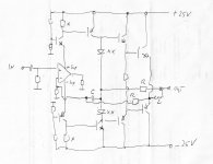
Current dumping can be simplified. Attachment is a sketch of a design.
The Opamps supply rails are used as outputs.
The problem is to keep bias of dumpers in class B.
A thermal coupling of diodes marked XX on heatsink will not ensure that.
Assume resistors marked X set bias as such that at room temperature idling current is 0 then the bias would not be
dynamically stable. Fast thermal runaway cannot be prevented.
Thus an overload or clipping protection circuit is mandatory.
It won't get much better with vertical FETs.
Hans Dieter
Attachments
hahfran,
if you`ll excuse me, consider this design instead, you won`t regret it.
http://www.diyaudio.com/forums/attachment.php?s=&postid=1649849&stamp=1225821617
if you`ll excuse me, consider this design instead, you won`t regret it.
http://www.diyaudio.com/forums/attachment.php?s=&postid=1649849&stamp=1225821617
@hahfran
a working circuit is already posted here:
http://www.diyaudio.com/forums/showthread.php?postid=1526736#post1526736
but....it's not too close (sound quality point of view) to the Quad-mosfet...as i've built both of them
a working circuit is already posted here:
http://www.diyaudio.com/forums/showthread.php?postid=1526736#post1526736
but....it's not too close (sound quality point of view) to the Quad-mosfet...as i've built both of them
Yes that's much the same but no surprise it's a simple straight forward stuff. But I would not use darlingtons because one has to take care that in the power stage the BJTs have ton==toff
therefore I used the resistor between the emitters of the drivers.
However my design objective is first of all a particular sequence of the amplitude of harmonics close to the sprectrum of an acoustical music instrument the THD is not a big issue, next is the amp must fit into the speaker box backside enclosure and thus the size of heatsinks is limited and hence dissipation and output power. The famous equations of Quad hold for static sine signals
but possibly not for transient signals to evaluate is a matter of listening tests . Taking distortion reading with sine waves tells close to nothing about the musical qualities of an amp.
Very nice design. I've always been partial to the QUAD 405 and variations. I’ve built a few variations but was never entirely successful with MOSFET outputs due to the gate source bias. The 22 ohm resistor is a good way to overcome this with lateral mosfets.
In this version, and assuming very good sharing on the output devices, the peak current per device at 200 watts rms and 8 ohms would be 1.76 amps. At 4 ohms that would increase to 2.5 amps. The n channel devices will always have sufficient bias as the driving stage can supply plenty of current across the 47 ohm resistor. The current sink at 55 mA can provide 3.8 volts bias, which drops to 3.3 volts with the source resistors. From the output data sheet, it seems like the typical part requires almost 4 volts bias to develop 2.5 amps. Have you selected the output devices, or has this ever been an issue in the amplifiers you’ve built?
Again, very nice design and please do not take this as a criticism, just a question.
Thanks!
hahfran,
Very much agreed.Taking distortion reading with sine waves tells close to nothing about the musical qualities of an amp. THD is not a big issue
You won`t get it it with that IC.However my design objective is first of all a particular sequence of the amplitude of harmonics close to the sprectrum of an acoustical music instrument
jonusgrumby said:Very nice design. I've always been partial to the QUAD 405 and variations. I’ve built a few variations but was never entirely successful with MOSFET outputs due to the gate source bias. The 22 ohm resistor is a good way to overcome this with lateral mosfets.
In this version, and assuming very good sharing on the output devices, the peak current per device at 200 watts rms and 8 ohms would be 1.76 amps. At 4 ohms that would increase to 2.5 amps. The n channel devices will always have sufficient bias as the driving stage can supply plenty of current across the 47 ohm resistor. The current sink at 55 mA can provide 3.8 volts bias, which drops to 3.3 volts with the source resistors. From the output data sheet, it seems like the typical part requires almost 4 volts bias to develop 2.5 amps. Have you selected the output devices, or has this ever been an issue in the amplifiers you’ve built?
Again, very nice design and please do not take this as a criticism, just a question.
Thanks!
Thank you Tom for input !
I'm always open to any suggestion which may improve this design. 🙂
47ohm resistor is part of current dumping bridge.
The bias resistor is R19 22ohm for laterals and 100ohm for IRFP verticals.
The full output power is given by class A stage voltage swing and not by voltage bias.
As I already mentioned, I run this amplifier in class AB with very little bias in class A. - Ids for laterals is ~40mA and for IRFP 60-100mA
But this is a error correction amplifier and should don't care too much about bias and therefore I don't match or select output devices. 😉
Regards,
Tibi
Hi I have just stumbled on this thread and thought I would make a comment....
In the late 70s, guys I worked with were building 'Edwin' current dumping amps from Elector magazine and were very happy with the output.
I heard that a JVC amp which had just come out was a 'copy' of the current dumping principals from the Quad 405.
This JAS55 model has been my main amp for 30 years and still sounds beautiful.
This uses monolithic darlington outputs from STK. Good for '60W RMS' but I have upgraded them to STK0080's which handle a bit more.
I have only ever seen one, and I have never seen one on ebay.
Anyone know of them?
Cheers
Lumba Ogir said:hahfran,
Very much agreed.
You won`t get it it with that IC.
Yes I know I don't like ICs in audio signal path.
I will try a design without IC only discrete BJTs and as few as possible.
hahfran,
I understand that you want to use bipolar output devices, the proposed topology is, however, superior to yours and to the Quad variants, producing a harmonic spectrum you looking for.
I have no interest in persuading you, it`s just a hint.
I understand that you want to use bipolar output devices, the proposed topology is, however, superior to yours and to the Quad variants, producing a harmonic spectrum you looking for.
I have no interest in persuading you, it`s just a hint.
Lumba Ogir said:... the proposed topology is, however, superior to yours and to the Quad variants, producing a harmonic spectrum you looking for.
I...
Hello Lumba,
Can you sustain your affirmation ?
Have you built both and measured/compared ?
If not, please be restrained in such affirmations. 🙂
Regards,
Tibi
Lumba Ogir said:hahfran,
I understand that you want to use bipolar output devices, the proposed topology is, however, superior to yours and to the Quad variants, producing a harmonic spectrum you looking for.
I have no interest in persuading you, it`s just a hint.
The clean ground feature is certainly interesting. Many are unaware how wiring of ground affects performance of an amp far more than circuit topology.
I have an old but fundamental essay on this item.
I am not too much enthusiastic about FETs more about ring emitter BJTs. The Vgs/Ids is almost exponential while for ring emitter BJT the Ib/Ic is almost linear.
My present favorite is a "reborn" Quad 303 but I want to examine
current dumping also.
Around end of december I will have some free time to examine
several different topologies.
Hans Dieter
- Home
- Amplifiers
- Solid State
- QUASAR a reborn design