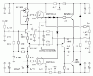
Re: QUASAR a QUAD405...
bulgin,
Very nice restoration !
Regards,
Tibi
bulgin said:And a last
bulgin,
Very nice restoration !
Regards,
Tibi
Re: The ugly IRFP version :-D
Hi Tvicol,
being I a fan of current dumping applications, I appreciate your job very much.
Is the value of R19 right? With a current of about 27mA the dumpers are biased at around 6 volts that could be too much.
Regards,
Pintur
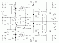
tvicol said:Here is a picture with one prototipe I used for tests.
This is with vertical mosfets IRFP240/9240.
In this version R3=10Kohm; R10=100ohm; R17=22ohm; R19=220ohm
and only two pairs of IRFP output mosfets.
The sound with IRFP's is very good as well.
Large heatsinks must be used in order to avoid vertical MOSFET run avay.
Regards,
Tibi
Hi Tvicol,
being I a fan of current dumping applications, I appreciate your job very much.
Is the value of R19 right? With a current of about 27mA the dumpers are biased at around 6 volts that could be too much.
Regards,
Pintur
Re: Re: The ugly IRFP version :-D
Thank you, Pintur !
The N and P MOSFET dumpers will be biased at aprox +3V respectively -3V.
For a vertical MOSFET this is not too much, as they have a gate threshold voltage between 2 and 4V.
The error correction circuit will be able to handle a large variation in dumper biasing. In fact I built several vertical MOSFET versions and with same bias resistor I got dumpers Ids between 19mA and 86mA. If you manage to put a 500ohm pot across R19 and bias dumpers to aprox 40-50mA will be excellent. Afther that replace with an equivalent noninductive resistor (Mills).
The single problem with verticals is that they trend to increase Ids with temperature. A solution is to reduce R19 and have a coule of diodes in series with. These diodes must be in direct contact with heatsink. Another is to use a superdiode.
Personally I will go for a sigle resistor, because for my ears this will give the best sonic results. 😉 The downside are the heatsinks which need to be really big.
Regards,
Tibi
pintur said:
Hi Tvicol,
being I a fan of current dumping applications, I appreciate your job very much.
Thank you, Pintur !
pintur said:
Is the value of R19 right? With a current of about 27mA the dumpers are biased at around 6 volts that could be too much.
Regards,
Pintur
The N and P MOSFET dumpers will be biased at aprox +3V respectively -3V.
For a vertical MOSFET this is not too much, as they have a gate threshold voltage between 2 and 4V.
The error correction circuit will be able to handle a large variation in dumper biasing. In fact I built several vertical MOSFET versions and with same bias resistor I got dumpers Ids between 19mA and 86mA. If you manage to put a 500ohm pot across R19 and bias dumpers to aprox 40-50mA will be excellent. Afther that replace with an equivalent noninductive resistor (Mills).
The single problem with verticals is that they trend to increase Ids with temperature. A solution is to reduce R19 and have a coule of diodes in series with. These diodes must be in direct contact with heatsink. Another is to use a superdiode.
Personally I will go for a sigle resistor, because for my ears this will give the best sonic results. 😉 The downside are the heatsinks which need to be really big.
Regards,
Tibi
Hi Tvicol,
thanks for your detailed replay.
To avoid the use of a large heatsink with vertical mosfets (lateral are too difficult to find) and being hard to obtain a stable circuit with darlingtons, as per your experience could it be possible to arrange the class A stage in order to drive directly a complementary couple of bjts dumpers with no risk of overload?
Regards,
Pintur
Pintur,
Yes, it is possible to arrange the class A stage to support complementary BJT. This can be done in several ways, it is just up to your imagination.
But still, I will prefer a low power class A stage with very good linearity. 😉
http://www.tme.eu it is a good place to buy lateral mosfets and many other components. 🙂
Regards,
Tibi
Tvicol,
thank you very much for your feedback.
You are right, as the performances of the entire amp depend on the quality of the class A stage, it's preferable do not stress it with extra-work.
Regards.
Pintur
thank you very much for your feedback.
You are right, as the performances of the entire amp depend on the quality of the class A stage, it's preferable do not stress it with extra-work.
Regards.
Pintur
Hi Tvicol,
I am very interested by your Quad reborn versions and have compared them with the original design accurately.
As well as I could ascertain in the mosfets versions the two diodes between the output of the class A stage and the base of the upper dumper are omitted.
If I am right in the Quad 405 the function of these diodes was to let the collector of TR7 be still above the output level, in order to control the speakers although the dumpers are open.
Could you kindly explain your choice?
Regard,
Pintur
Pintur,
Thank you for your interest in my QUAD approach ! 🙂
The two diodes you are talking about, have been used by QUAD in order to symmetrical drive the dumpers.
In my amplifier I prefer to not use any diodes in the load of class A stage. I know that MOSFET dumpers will be a little "unbalanced", but IMHO this is not a problem as long they are biased in class A by a small amount of current.
Regards,
Tibi
Hi Tibi,
Your explanations are always exhaustive at all.
Now the reason why the mosfet dumpers are biased so close their threshold gate is clear to me.
If vertical types are employed along this way it ‘s lost one of the attractive peculiarities of the Quad invention, that is either the absence of thermal compensation or the use of big heatsinks. But this is compensated by the better linearity of the class A stage that now has a less heavy task in driving the dumpers.
Lateral should be the final solution.
Compliments for your work on the smart 405 that is still impassioning so many people everywhere.
.
Regard.
Pintur
Errata corrige:
- obviously in the previous post I had the intention to write “… NOT BIG – instead of BIG – heatsinks” about the peculiarities of the Quad405.
I regret my oversight.
Pintur
- obviously in the previous post I had the intention to write “… NOT BIG – instead of BIG – heatsinks” about the peculiarities of the Quad405.
I regret my oversight.
Pintur
Welcome Tibi to our heretical camp!
I made my first A+C amp in 1976 "cheating" with approximation: failed to get satisfactory results from biased to class AB amplifier that uses the same output transistors for class A and for class B I decided to go with approximation of transfer function and combined very clean resistively loaded class A amp with class C one that helps to drive higher currents. I was a student then and thought "If big guys don't go such a way something is wrong with it". Later I've discovered that the approach was patented by Peter Walker, called Quad-405, but despite of much better quality of sound and more elegant design the industry did not go such a way.
My latest project uses this approach going a bit further: class A amp is more powerful, and instead of 3-step approximation (A+C) I use 5-step one (A+C+C). It helps me to achieve enormous current drive capabilities for real complex loads with very few output devices, also I don't need an active overcurrent protection that gives nasty clipping on peaks when I hear PA amps made for professionals by modern manufacturers... I once had to replace binding posts and a screwdriver, but the amp continued to sound, clean and pleasing.
Good job, congratulations!
Version 11i
Latest tested version is 11i.
CC stage for cascode T3,T4 was improved. Now T4 can be removed and T3 replaced with ZTX653, this will sound equally good as cascode stage.
Operational changed to LME49870 which is +/-22V version of LME49710.
R37 will increase class A stability.
Regards,
Tibi
Latest tested version is 11i.
CC stage for cascode T3,T4 was improved. Now T4 can be removed and T3 replaced with ZTX653, this will sound equally good as cascode stage.
Operational changed to LME49870 which is +/-22V version of LME49710.
R37 will increase class A stability.
An externally hosted image should be here but it was not working when we last tested it.
Regards,
Tibi
Hi Tibi,
compliments for experimenting different ways to extract the great potentialities of the glorious 405.
I too am playing with feedforward error correction, principally in order to short the signal path.
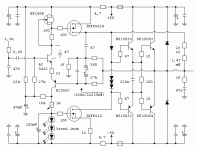
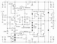
In my approach the frontend is now a Rush cascode, a Hexfet is employed in the class A output, servo has been removed, values of bridge components are the same as 306, 606, 707, 909 ones while dumpers are both NPN like in the classic Quad configuration.
This schematic has not yet been tested, values to be verified.
What is your think about?
Regards,
Pintur
Attachments
Hi Pintur,
Your approach is very good !
I see that you want to keep class C operation of output stage. I suggest you to go closer to class B by adding one more diode between output base dumpers. This will reduce noise and increase overall amplifier stability.
Another observation is related to class A stage bias. In order to have a better control and reduce noise you may consider a solution with TL431 or 2-3 red LED's in series and a potentiometer for bias tuning.
The input stage bipolar & jfet it looks to me more like a SRPP.
Regards,
Tibi
Hi Tibi,
thanks for your feedback. You are right, the frontend can be seen like a combination of Rush cascode and SRPP, with the jfet doing the functions of constant current source and follower to assure lower impedance for driving the IRF.
Adding another diode between the bases of dumpers is a nice idea, but I prefer to avoid either the use of bigger heatsink or thermal compensation. However I agree that the job of the class A stage to correct the errors would be much easier.
I am looking forward to test the circuit in order to experiment your suggestions and the variations in the dumpers stage that you are kindly sharing with 405 fans.
I am also curious to try discrete darlingtons, it may be they do not oscillate thanks to the lower NFB of this schematic compared to the original one, where the majority of the tension gain is granted by the IC in the front.
Regards,
Pintur
Attachments
hallo tvicol
I have some questions for You:
-Why T1 and T2 are so powerful BD139/140?
-Have You test and can you suggest an alternative in the BC,MJe etc. family for 2SA970 2SC2240?
-Have you made a real world measures of your creature?
I'm specially interested in S/R performance and THD at various levels,frequency and loads.
Thank You and regards.
semola
semola said:hallo tvicol
I have some questions for You:
-Why T1 and T2 are so powerful BD139/140?
Hello Semola,
In normal conditions T1 and T2 will need to dissipate around 400-500mW
A 1-2W transistor (like ZTXxxx) will run out of soa without any heatsink option.
BD139/140 have enough dc current gain Vceo is 80V - above our requirements - and will handle this power even without heatsinks.
Here, a good replacement for BD139/140 are MJE340/350.
semola said:
-Have You test and can you suggest an alternative in the BC,MJe etc. family for 2SA970 2SC2240?
-Have you made a real world measures of your creature?
I'm specially interested in S/R performance and THD at various levels,frequency and loads.
Thank You and regards.
semola
You can replace 2SA970 with BC560C and 2SC2240 with BC546C.
I did THD measurements at 1kHz using HP339A.
At 1kHz 1W/8ohm THD was under analizor scale.
At 1kHz 100W/8ohm THD was ~ 0.01%
Anyhow, I need to get a better THD analyser as my feeling was that this tool is not very accurate.
SR will be measured as soon I'll get a function generator.
Most important is that the amplifier sound very detailed, clean, fast and with huge micro and macro dinamics.
Regards,
Tibi
- Home
- Amplifiers
- Solid State
- QUASAR a reborn design


