No comments on the RIAA feature?
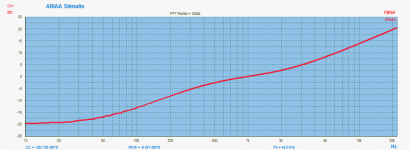
You asked for... ARIAA.. using upcoming V3.50 and using the FFR (Fast Freq. Responce) feature 😀
Hp
Attachments
To those who know more than I do, I have two questions:
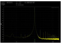
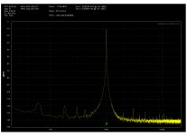
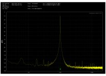
1) Why is the bottom of the sine wave so narrow from the internal oscillator and wider on the external oscillator? (looking at the -100 to -130+ dB range on the 1K signal)
2) Why is there some 60Hz noise on the images with the external oscillator. I'm assuming cable routing or some AC device close by (or maybe agdr's cat from earlier pictures!)
Thanks everyone for the information!
Twisted pair will help with noise reduction during tests of DUT.
Use a twist (and other popular wires) to reduce EMI/RFI | EE Times
THx-RNMarsh
Use a twist (and other popular wires) to reduce EMI/RFI | EE Times
THx-RNMarsh
THD
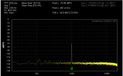
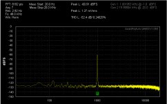
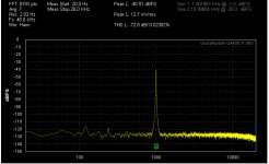
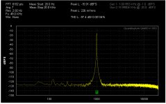
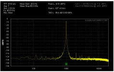
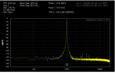
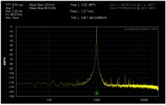
I own a QA400 almost ca. 2.5 years, and I only noticed this now.
As the input signal reduced down from 0dBfs, the THD improves, and it improves a lot. Am I doing something wrong?
The signal is coming from Victors 1kHz oscillator.
I own a QA400 almost ca. 2.5 years, and I only noticed this now.
As the input signal reduced down from 0dBfs, the THD improves, and it improves a lot. Am I doing something wrong?
The signal is coming from Victors 1kHz oscillator.
Attachments
Monotonicity
Measuring a CD player with a test CDR made in CoolEdit shows perfect monotonicity (I think it's called that).
I know some players don't like the 0dBfs signal, so early I included in the measurements the -2dBfs level.
Going down on the level scale I have, 0, -2, -6, -15, -40, -60, -70, and -80dBfs in the pictures.
Attachments
-
 Esoteric VRDS Neo 1k -70dB.jpg155.9 KB · Views: 124
 -
 Esoteric VRDS Neo 1k -60dB.jpg156.4 KB · Views: 125
 -
 Esoteric VRDS Neo 1k -40dB.jpg156.7 KB · Views: 137
 -
 Esoteric VRDS Neo 1k -15dB.jpg158.5 KB · Views: 145
 -
 Esoteric VRDS Neo 1k -6dB.jpg160.4 KB · Views: 135
 -
 Esoteric VRDS Neo 1k -2dB.jpg159.9 KB · Views: 168
 -
 Esoteric VRDS Neo 1k 0dB.jpg165 KB · Views: 416
 -
 Esoteric VRDS Neo 1k -80dB.jpg156.3 KB · Views: 138
I dont think you are doing anything wrong. I found similar errors. So, I had to compare to more accurate instruments to see the 'real' values for thd.
-RNM
-RNM
I dont think you are doing anything wrong. I found similar errors. So, I had to compare to more accurate instruments to see the 'real' values for thd.
-RNM
Thanks for the reply, and what did you come up with?
What max dBsf level the most believable? Would be nice to know.
I saw that around -10dBfs prvide the lowest THD reading.
The measurements are repeatable, so for comparison is OK, but not for absolute measurements.
I wonder from where the problem arises , is the circuits (if any) before the ADC, or maybe some kind of power supply problem (to low voltage)?
I guess it's no circuit diagram available for the unit.
Regards.
Late to the party but simply put, QA makes use of coherent sampling(the oscillator frequency is always set according to the fft bin length).
If you take a look at QA measurement plots, the 1khz test frequency is never matched at 1khz but offset a little so that an integer number of cycles is always captured within the FFT length set. This results in almost no widening of the skirt. O
You can easily do the same with a calculator and a little math in ARTA or similar programs if you are using a DAC. Using a QA unit does this automatically for you.
Who is the unknown Matt?
Now I'm wondering also. I"ll check this afternoon or evening hopefully.
I have the lowly QA400. I'll try to duplicate some of the plots y'all have run.
I can verify, compare the QA400 information with the Shibasoku 725D,
an HP339a, and an old analyzer that runs on the DOS system. It will do an
FFT but I have to set it up to do THD, THD + N or SINAD measurements
separately.
OBSERVATION
I've noticed with the 725D and it may also be applicable to 725 b/c units.
When I am running through and making a lot of measurements over time
the 725D starts to exhibit higher distortion readings with the some of the
filters engaged. My solution is to keep the filters off while I set up the
measurements and check levels etc., then when ready engage the filters
and note the readings.
As, the rain here in Texas has stopped for the time being, I have to get
some other stuff done before I can do the fun stuff. Film at 11.
QUESTION
When setting a notch filter what is its optimum bandwith, or offset?
For example, if I want to set a 1kHz notch with a depth of -40dB I can
set it's bandwidth. I set the center frequency to 1000Hz.
Then, do I want offsets: +10Hz -10Hz, +20Hz -20Hz, +50Hz -50Hz?
Or something less like +1Hz -1Hz?
Last edited:
I wanted to add how much I appreciate my colleagues here.
By its very nature these investigations tend to force us to spend time
alone trying to find answers to our questions. I find it refreshing
and healthy to share, reflect, debate, inquire, learn, and all that
and even more with y'all.
Cheers,
Sync
By its very nature these investigations tend to force us to spend time
alone trying to find answers to our questions. I find it refreshing
and healthy to share, reflect, debate, inquire, learn, and all that
and even more with y'all.
Cheers,
Sync
The good news is I don't feel so bad now about the waterboarding incident
with the HP 339A that I had a while back. This graphic, Fig 4 in a follow on
article from which I linked from RNs post, reminded me if those Fun-N-Games.
I recognize the signs of clipping onset on an FFT.
Enjoy: FFT: Equations and history | EDN
with the HP 339A that I had a while back. This graphic, Fig 4 in a follow on
article from which I linked from RNs post, reminded me if those Fun-N-Games.
I recognize the signs of clipping onset on an FFT.
Enjoy: FFT: Equations and history | EDN
Thanks for the reply, and what did you come up with?
What max dBsf level the most believable? Would be nice to know.
I saw that around -10dBfs prvide the lowest THD reading.
The measurements are repeatable, so for comparison is OK, but not for absolute measurements.
I wonder from where the problem arises , is the circuits (if any) before the ADC, or maybe some kind of power supply problem (to low voltage)?
I guess it's no circuit diagram available for the unit.
Regards.
There is a lot of great info here: Active Twin-T notch filter
THx-RNMarsh
This is a tremendous article. Long ago, in the 70's, I used passive and active twin T filters to measure distortion in my amplifiers before I had a THD analyzer. I only measured at 1kHz and 20kHz, with dedicated fixed-frequency twin T filters.
I used a different type of active twin T filter, however. The one in the article uses positive feedback to sharpen the notch and reduce attenuation at the harmonics, especially important for the second and third. Mine used a different trick to achieve this. It used negative feedback around an otherwise normal twin T (the shunt components just went to ground, just like in a passive twin T). 20dB of negative feedback reduces the undesired attenuation by a factor of about 10. Unfortunately, it also correspondingly reduces the depth of the notch by 20dB. I was unaware of the positive feedback version at the time.
So here is my question (probably answerable by SPICE if I was not so busy right now): Does the positive feedback version also suffer reduced notch depth due to the feedback?
Cheers,
Bob
I think it increases the notch. I have a Sim of the Shibasoku 725 variant and I can share. I think I did.in the Shibasoku thread.
Sent from my SGH-M919 using Tapatalk
Sent from my SGH-M919 using Tapatalk
This is a tremendous article.
So here is my question (probably answerable by SPICE if I was not so busy right now): Does the positive feedback version also suffer reduced notch depth due to the feedback?
Cheers,
Bob
I think it increases the notch depth rather than reduces it.
-RNM
I think it increases the notch depth rather than reduces it.
To clarify, if we were trying for a notch depth of -20dB we would
get a notch depth of something like -23.941 instead?
Because it increases the notch depth.
Cheers,
Sync
Actually positive feedback decreases the notch depth.
We give some depth up for sharper shoulders.
I sim'd a circuit that used a Bridged T rapped in the feedback of a op amp to form a narrow band pass to tighten up the shoulder but never got around to building physical model. The Bridged T is tuned just above the notch frequency.
It's an idea I got from the original Shibasoku patent.
Sharper or higher Q is what we want. The pos feedback should do that for us. Could be tricky if you also went for high notch depth (osc). This is were a good sim will be useful.
THx-RNMarsh
THx-RNMarsh
Thanks, I'm reading right now.
This is a tremendous article. Long ago, in the 70's, I used passive and active twin T filters to measure distortion in my amplifiers before I had a THD analyzer. I only measured at 1kHz and 20kHz, with dedicated fixed-frequency twin T filters.
I used a different type of active twin T filter, however. The one in the article uses positive feedback to sharpen the notch and reduce attenuation at the harmonics, especially important for the second and third. Mine used a different trick to achieve this. It used negative feedback around an otherwise normal twin T (the shunt components just went to ground, just like in a passive twin T). 20dB of negative feedback reduces the undesired attenuation by a factor of about 10. Unfortunately, it also correspondingly reduces the depth of the notch by 20dB. I was unaware of the positive feedback version at the time.
So here is my question (probably answerable by SPICE if I was not so busy right now): Does the positive feedback version also suffer reduced notch depth due to the feedback?
Cheers,
Bob
Bob I'm interested in the negative feedback version. Do you have anything on it can you put up here? Diagrams etc.
- Home
- Design & Build
- Equipment & Tools
- QuantAsylum QA400 and QA401