Actually no a 1 mega ohm could not be used. The resistor is connects to Vcom to bias the op amp input. The noise rises significantly with resistance. Mat tried it with higher value resistors but the noise is too high. They would have use 1k if they could get away with it.
It really depends on how you drive it and how you test the noise. If you really want to measure the noise of the QA400, you need to terminate the input with the normal source impedance before reading.
Important to note. You CANNOT look at the noise by leaving the input open. If you leave the input open, then you read the full thermal noise of the 1M resistor. Make sure that person terminate the input when reading the noise of the QA400.
The noise is calculate with the parallel combination of the source's output impedance in parallel with the input impedance. The point is if you have 1M resistor for biasing the input, you plug in a device with 1K output impedance, your noise calculation is 1M parallel to 1K which is just 1K. If one found using 1M increases the noise with device plugged in, something is really wrong.
Quite so. The input impedance is what ever the DUT output impedance is plus what ever
series Z at the QA400 input. But because of the Vcom bias arrangement the noise rises with the Vcom supply resistance and this is QA keep the value low. I worked with Mat on this a bit
just before the QA400 was officially released. The Vcom is extremely sensitive to the reactive and resistive load on it as well. It shapes the noise floor curve of the ADC. Any influence from input loading plays a part in the noise shape.
I don't understand what is Vcom bias arrangement. I don't have the schematic. But I cannot see any reason the input is nothing but a simple voltage buffer driving the ADC. Maybe you can explain a little more on what they are doing.
I design a lot of data acquisition systems, I worked 3 years for LeCroy that produce all sorts of digitizer and digital scope in the 80s. In my experience, the front end is just a simple amplifier ( be that it's high speed or low noise precision) driving the input of the ADC. QA400 uses a JFET input opamp OPA1642. The input resistor just to keep the input at a fixed voltage.
Hardware of this kind of circuit should be very simple and straight forward. It's all on the software control all the function and calculation. That's why people can use any sound card, the Personus or others to do the same thing. The hardware is very simple. You need an ADC to read the signal and have a way to interface into the computer, you are in business.
Last edited:
The QA400 input is simple. The QA400 ises a single supply so the digital stuff needs to be offset ("Vcom"). There may be some other noise effects (current noise with the Jfet input) that impact the circuit and in general high Z stuff is an invitation for problems if it can be avoided. I encountered the two resistors and their impact on the input Z and promptly forgot the whole thing. The levels are great for mobile electronics (phones, portable speakers etc.) which is the primary market in China. The boards I sketched out were to address the limitations of that.
Most users can work around the limitations pretty easily with a little effort.
I'll just wait for the QA405 at this point since its much more versatile. It may also get a standard sound card interface.
Most users can work around the limitations pretty easily with a little effort.
I'll just wait for the QA405 at this point since its much more versatile. It may also get a standard sound card interface.
I actually looked at the data sheet of the CODEC CS4272 used in the QA400 in order to put this into some context:
http://www.cirrus.com/en/pubs/proDatasheet/CS4272_F1.pdf
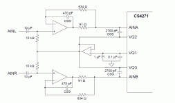
If you look at Fig 12 page 32. Vcom is just the common mode voltage to bias the input of the buffer to some where in the middle between ground and Vcc because the CS4272 is running on single supply voltage.
The gain of the two buffer is just unity. the 91ohm and the 470p cap is just to prevent the opamp from oscillating when driving capacitor load. There is ABSOLUTE NO reason the two 10K resistor cannot be change to 1M. You even can extend the frequency down to lower frequency. There is no excuse on higher input resistance cause offset as OPA1642 has jFET input and offset does not matter for AC analyzing. Only extreme offset cause clipping on one side of the ADC, nothing more.
as I expected, this is a very simple circuit, just a simple buffer. I am surprised they did not bring out the differential input. Maybe, they want to sell the QA190!!!
It is super easy to put the attenuator at the front end if they want to. I am more than willing to pay $10 more if they do that.
I suspect whoever claim 1M cause noise, ran the noise reading with the input open. Then you read the full thermal noise of the 1M resistor.
http://www.cirrus.com/en/pubs/proDatasheet/CS4272_F1.pdf
If you look at Fig 12 page 32. Vcom is just the common mode voltage to bias the input of the buffer to some where in the middle between ground and Vcc because the CS4272 is running on single supply voltage.
The gain of the two buffer is just unity. the 91ohm and the 470p cap is just to prevent the opamp from oscillating when driving capacitor load. There is ABSOLUTE NO reason the two 10K resistor cannot be change to 1M. You even can extend the frequency down to lower frequency. There is no excuse on higher input resistance cause offset as OPA1642 has jFET input and offset does not matter for AC analyzing. Only extreme offset cause clipping on one side of the ADC, nothing more.
as I expected, this is a very simple circuit, just a simple buffer. I am surprised they did not bring out the differential input. Maybe, they want to sell the QA190!!!
It is super easy to put the attenuator at the front end if they want to. I am more than willing to pay $10 more if they do that.
I suspect whoever claim 1M cause noise, ran the noise reading with the input open. Then you read the full thermal noise of the 1M resistor.
Last edited:
The QA400 was designed to meet a particular price target. I can assure the people at QA know what their doing. There is quite a number of heavy weight industrial guys involved Motorola and Microsoft to name a couple. Like Demian said it was designed to target a market in China. Assembly lines as part of they quality control. As a side market it's offered to hobbyist. I pretty sure most of us here understand loading inputs when taking noise measurement. It's kind of elementary don't you think.
If you read the data sheet further you'll notice Crystal recommends not to exceed 1uF of capacitance for filtering on the VCOM pin. If this maximum value is exceeded the entire noise shape of the ADC changes. The noise increases starting at about 1kHz and rises with an upward slope as the frequency approaches 10Hz. Kind of looks like 1/f noise but it's not.
This effect has nothing to do with what op amp is used for a buffer and has nothing to do with input loading. It's inherent to the VCOM of the ADC.
I was in the beta testing group for the QA400 and I introduce the QA400 to the DIYAudio forum. I have substituted the 10k resistor for 100k resistor from the VCOM to op amp input and the noise went up regardless of input loading.
Do you have the schematic of the front end of QA400? They must be doing something drastically different from the sample circuit given by the Cirrus Logic.
Last edited:
Well Allan you came her asking for help but what your doing is just talking down to us.
You have no idea of my back round or knowledge or anyone else for that matter. I'm quickly loosing interest.
You have no idea of my back round or knowledge or anyone else for that matter. I'm quickly loosing interest.
Well Allan you came her asking for help but what your doing is just talking down to us.
You have no idea of my back round or knowledge or anyone else for that matter. I'm quickly loosing interest.
No, I am not talking down to you. I am just having a discussion. If I sound that way, I apologize. I like to talk theory and find out why. I am leaning to buy this one, that's why I am so into this.
I really want to find out because with 10K, it is hard to do current limiting as you have to drive with low impedance. If I can get it to have high impedance, I can use a series resistor to drive the input and protect the QA400. I asked the same question to them also, they said they are planning to increase the resistance.
Do you have the schematic of the front end? I am just curious.
SORRY
Last edited:
Richard or Demian, didn't y'all change a couple of those caps
at the input and and got some better results than the stock caps?
Do you recall what you replaced them with if you did?
THD & THD +N Calculations.
V1.2 still has the same problems...i can't get calculation
or the calculation do not work sometimes. ; (
at the input and and got some better results than the stock caps?
Do you recall what you replaced them with if you did?
THD & THD +N Calculations.
V1.2 still has the same problems...i can't get calculation
or the calculation do not work sometimes. ; (
I forgot the VCOM is buffered by an OPA1641. You can swap the 10k resistor for whatever you want.
The code used is the CS4272. However QA used the recommended circuit fron the data sheet for the CS4271 mono codec. It the same codec as the CS4272 less one.
Substitute my drawing of the QA400 input circuitry for the CS4271 schematic as necessary.
Everything past the input caps of the 4271 schematic is correct.
The op amp QA used are OPA1642 and OPA1641 or 2 for the VCOM buffer.
Attachments
Richard or Demian, didn't y'all change a couple of those caps
at the input and and got some better results than the stock caps?
Do you recall what you replaced them with if you did?
THD & THD +N Calculations.
V1.2 still has the same problems...i can't get calculation
or the calculation do not work sometimes. ; (
I swapped in a polypropylene in for Mat to see if the distortion would improve but there was no difference so the 10uF ele went back in. ELE have a bad rep that's proving to be false.
I forgot the VCOM is buffered by an OPA1641. You can swap the 10k resistor for whatever you want.
The code used is the CS4272. However QA used the recommended circuit fron the data sheet for the CS4271 mono codec. It the same codec as the CS4272 less one.
Substitute my drawing of the QA400 input circuitry for the CS4271 schematic as necessary.
Everything past the input caps of the 4271 schematic is correct.
The op amp QA used are OPA1642 and OPA1641 or 2 for the VCOM buffer.
Thank you.
Please report on your progress with this.
It's going to be a few weeks. I am still waiting for the 0.22ohm resistors from Mouser to finish the OPS board, then I have to bring the amp up and make sure it works. Testing THD is the last thing on the development. I want to buy it so as soon as I get it, I am ready to use to make sure I stay in the 15 days return period if something goes south with the unit. You never know about the brand new stuff, I have my share of new stuff breaking down on me. Never trust the stuff until they last over two weeks.
Ha ha, The laptop I am using now is the 4th one!!! I had three brand new ones that went south all within the return period. Real problems too. One HP had multiple key sticking developed in 2 weeks. A Dell went blue screen on me. Then the first Lenovo had a key popped out if you type at certain spot!!! All brand new and all had real problems.
Knock on wood, This Lenovo been working for over a month and it's perfect. I am just so tired of loading all the programs, then had to wipe it clean to return it.
I swapped in a polypropylene in for Mat to see if the distortion would improve but there was no difference so the 10uF ele went back in. ELE have a bad rep that's proving to be false.
the main issue is when there is voltage drop across the electrolytic cap and then the distortion is high. Not much issue when the C is large enough..... but tant type are always poor.
However, electrolytics do vary in quality so check first.
It can have an affect show up in coupling but only below -90dB thd.
THx-RNMarsh
Even if you leave the 10uF and 10K alone, the high pass frequency is 1.59Hz. At 16Hz, the distortion of the 10uF electrolytic should be negligible. Also, I read that electrolytic is not really that bad, not like ceramic or tantalum.
A side question, anyone bought the QA190? QuantAsylum replied that I can make the box myself as described to them, but if I get the QA190 it would be easier. But the QA190 do raise the noise floor a little particular at the low end.
E Also, I read that electrolytic is not really that bad, not like ceramic or tantalum.
I recently tested some newer type electro's and compared to old ones and NOS, they have improved.
cer and ta are still bad as ever
THx-RNMarsh
I recently tested some newer type electro's and compared to old ones and NOS, they have improved.
cer and ta are still bad as ever
THx-RNMarsh
NPO COG have to be separated out of this group.
- Home
- Design & Build
- Equipment & Tools
- QuantAsylum QA400 and QA401