I'd set up a window comparator for say 500mV +/-25%, plus a muting relay between the autoranger output and the QA400. You'd only unmute if the signal is within the window. I think you can set up the software such as to make it foolproof, like 'always muted unless...'.
Don't forget that the QA400 input seems pretty robust, I've seen lots of red LEDs indicating overload with no ill effects, but the 500mV is optimum for best performance, not that anything above that is destructive. So even if you want to have a safety clipper, it can be way above the optimum input level, like 3V, and pretty harmless wrt 500mV.
jan
I just came here and was going to say pretty much the same thing. As it was in the back of my mind when I asked the question... No output from the scaler/ranger until settled and then a small signal relay to connect it to the QA400. Nothing touches the signal being evaluated to the QA input that could cause distortion or limit performance in any way.
This 'feature' is what has been missing -- like making a single range DPM into an auto-ranging meter .... do same and all can be happy campers and live without fear.
THx-RNMarsh
Last edited:
This all works fine until the source switches level jumps +20 dB (can happen for many reasons). Then you switch to a higher range just in time to sniff the smoke.
For reference I'm attaching four different input protection circuits to study. The Shibasoku uses a 7W resistor to handle the 100V max. The Boonton will work up to 300V and uses big resistors as well. The Amber and the AP use light bulbs as does the newer Shibasoku. The lamps are preferable because the cold resistance is perhaps 20% of the hot resistance making for lower noise in operation while not sacrificing the high voltage protection. The challenge is finding lamps for the application. Finding a 220V 3W lamp that is small is virtually impossible in the US today.
Accepting that the QA400 is usable to -100 dB that puts it in the same class as a stock HP339 (and even an AP1 per specs) and it has a good 10-20 dB dynamic range without really degrading the specs I think this is overdoing it. Especially when the input box is 4-5X the size of the QA400.
Attachments
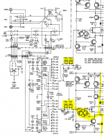
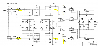
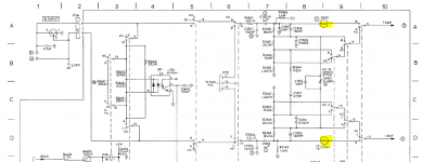
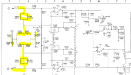
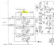
For a really good input current limiter see US patent 6970337. The cited references also provide good guidance on simpler (and not patent protected) solutions. Fluke too has several patents on this topic (e.g. US 5379176, US 5196980 and US 8582265), although more complicated and not necessarily suitable for low distortion applications.
Samuel
Samuel
This all works fine until the source switches level jumps +20 dB (can happen for many reasons). Then you switch to a higher range just in time to sniff the smoke.
For reference I'm attaching four different input protection circuits to study. The Shibasoku uses a 7W resistor to handle the 100V max. The Boonton will work up to 300V and uses big resistors as well. The Amber and the AP use light bulbs as does the newer Shibasoku. The lamps are preferable because the cold resistance is perhaps 20% of the hot resistance making for lower noise in operation while not sacrificing the high voltage protection. The challenge is finding lamps for the application. Finding a 220V 3W lamp that is small is virtually impossible in the US today.
Accepting that the QA400 is usable to -100 dB that puts it in the same class as a stock HP339 (and even an AP1 per specs) and it has a good 10-20 dB dynamic range without really degrading the specs I think this is overdoing it. Especially when the input box is 4-5X the size of the QA400.
Demian, I think any good autoranger would probably be as large or larger as the QA box. You'd have high-voltage DC blocking caps (large), couple of fuses if you want it to be balanced, a bunch of reed relays and probably rather large resistors for low thermal modulation. Anyway, such an autoranger would be useable for other analyzers or soundcards as well.
My way would be to use the Boonton card I have, and if it works, re-engineer that card for a better form factor.
The card does have a window comparator for the over/ underrange indication, which can be modified for different values. Most of the logic can be bypassed as you'd run the comparator outputs to inputs on the micro, for instance configured for interrupt-on-change.
The 6 (IIRC) switching relays can also be driven directly from the micro.
Right now I'm in the middle of two projects, one already lingering several years (direct drive amp for ESLs) and I HAVE to finish it this fall!
Jan
Get a tube amp... like dynaco... and cap couple off the push-pull plates to the push-pull ESL.... use B+ for the ESL HV. fast, easy and it worked with RTR ESL elements.
One could buy a cheap auto-scaling DVM and use its guts to drive reed relays off the decimal point outputs for scale/attenuator. ??
-RM
One could buy a cheap auto-scaling DVM and use its guts to drive reed relays off the decimal point outputs for scale/attenuator. ??
-RM
Last edited:
Get a tube amp... like dynaco... and cap couple off the push-pull plates to the push-pull ESL.... use B+ for the ESL HV. fast, easy and it worked with RTR ESL elements.
-RM
No I need at least 1500V RMS at 50mA. Will be solid state.
One could buy a cheap auto-scaling DVM and use its guts to drive reed relays off the decimal point outputs for scale/attenuator. ??-RM
That's another good idea - we really need to think out of the box here!
Jan
Here the results with 192ks.choco, perhaps run the same test(s) with the bandwidth up at 192, and avg = 0 and avg = ~10?
First two pictures show the QA direct wired in loop back.
Then the following pictures are showing the left chanel in direct wired loop back as reference and the right chanel with buffers and filter.
The results are showing the behavior at buffer output levels of:
180mVp (picture 3&4)
700mVp (picture 5&6)
6Vp (picture 7&8)
The input was always readjusted to provide 700mVp to the QA400.
Attachments
-
 Dual_RwithBuffer6Vp.JPG71.6 KB · Views: 161
 -
 1kHz_RwithBuffer6Vp.JPG70.3 KB · Views: 142
 -
 Dual_RwithBuffer700mVp.JPG71.9 KB · Views: 143
 -
 1kHz_RwithBuffer700mVp.JPG70.5 KB · Views: 142
 -
 Dual_RwithBuffer180mVp.JPG72.9 KB · Views: 145
 -
 1kHz_RwithBuffer180mVp.JPG71.8 KB · Views: 164
 -
 DualTone_directloopback.JPG71.3 KB · Views: 181
 -
 1kHz_directloopback.JPG70.1 KB · Views: 220
They would be much more useful with the resolution turned up. I think 65536 will show much more low level detail. Your current setting gives an 11 Hz resolution bandwidth so the noise floor is much higher.
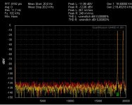
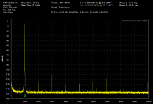
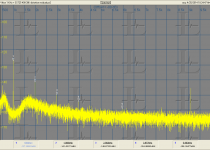
Here are the residual distortion measurements of my QA400
First is a selftest 48 KHz (left out to left in at -4 dBFS 995 Hz for all the measurements), 192 KHz selftest, 48 Khz using Viktor's 1 KHz oscillator and 192 KHz with Viktor's oscillator. Finally the same source through the Shibasoku 725 and captured with an EMU 1616M, scaled to dB below the full signal to verify that the source is much cleaner than the measurements (as Richard pointed out the residual distortions of the codec limit the system to around -100 dB to have confidence in the measurements).
I would expect most QA400's to get around this as a selftest. The cables that came with mine were an issue, the BNC's didn't quite fit so I ditched them and this was using a Pomona RG179 BNC to BNC cable.
Attachments
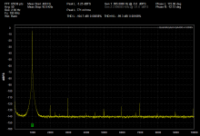
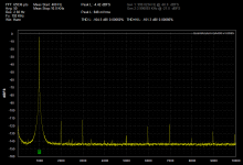
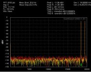
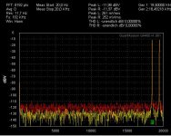
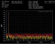
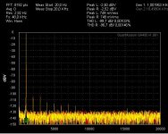
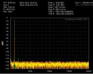
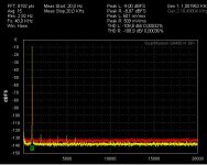
With such high levels (700...800mVrms) also my QA400 is showing similar distortion like yours. That's why I am using 500mVrms
Attached the loop back with Fs=48kHz with direct wiring.
First picture with 750mVrms.
Second picture with 500mVrms.
The 500mVrms, or better say 700mVpeak, appear to be the sweet spot of my unit.
So I am always adjusting to work with 700mVpeak, means for single tone the generator is 500mVrms (-6dbV or -9dbFS).
For dual tone each generator shall work at 250mVrms, means 350mVp, (-12dbV or -15dbFS) summing up to 700mVp at the highest moment.
How does your unit look at 700mVp instead over 1Vp?
Attachments
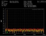
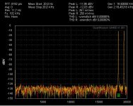
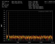
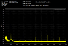
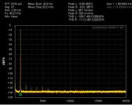
...averaging makes things less fuzzy. Sorry for ignoring that earlier.
First picture the self test a 500mVrms with FS=48kHz and avg=15.
Second picture also 500mVrms, FS=48kHz, avg=15, left chanel selftest for reference, right chanel with buffers and filter.
First picture the self test a 500mVrms with FS=48kHz and avg=15.
Second picture also 500mVrms, FS=48kHz, avg=15, left chanel selftest for reference, right chanel with buffers and filter.
Attachments
Last edited:
I'm using 600 mV and have not seen a dramatic change with lower levels. 500 mV to 600 mV is 1.5 dB. Please try a higher resolution on your measurements. 8192 is really low resolution, useful only for very fast acquisition of a measurement.
What I see is that the noise floor is higher with the buffers (not unusual at all). If you turn on THD+N you will see the difference in noise. As long as the noise is lower than what you are trying to measure by 6 dB or more you will get accurate measurements.
What I see is that the noise floor is higher with the buffers (not unusual at all). If you turn on THD+N you will see the difference in noise. As long as the noise is lower than what you are trying to measure by 6 dB or more you will get accurate measurements.
New version of the software released QA400.
https://www.quantasylum.com/content/Portals/0/UploadedFiles/setupQA400_1.0695.zip
https://www.quantasylum.com/content/Support/Downloads/QA400ReleaseHistory.aspx
https://www.quantasylum.com/content/Portals/0/UploadedFiles/setupQA400_1.0695.zip
https://www.quantasylum.com/content/Support/Downloads/QA400ReleaseHistory.aspx
No I need at least 1500V RMS at 50mA. Will be solid state.
That's another good idea - we really need to think out of the box here!
Jan
I used the PS transformer in the tube power amp and added a tripler to it for the high volt. Signal still came directly off the plates thru a coupling cap. Got a lot of voltage swing that way.... cheap. [And terminated the OP Transformer into a dummy R.] And, the signal was cleaner as it wasnt going thru an OPTransformer nor any audio step up transformer. . You could even replace the OPT with a resistive or inductors to make the OPT benign.
Here are some more rough idea generators -- example of what I was referring to..... you can use internal range selection, as shown, or use the range output ports to drive relays. Ports RA0,1,2 and ports shown as C1,2,3,4 would work as outputs to relay drivers to select attenuation.
View attachment Auto-scale 1.pdf
View attachment Auto-scale 2.pdf
View attachment Auto-scale 3.pdf
THx-RNMarsh
Last edited:
An electrostatic needs a balanced drive and needs voltage at low frequencies and current at high frequencies, the reason an amp for an ESL is so difficult. Using the primary of a transformer as the load gets a pushpull balancing effect and swing of up to 2X the supply rail, something else you need. The peak voltage should be almost the same as the bias voltage. More will get you into trouble, especially since the bias voltage should be very close to the dielectric (air) breakdown voltage to get the most efficiency. Its really non-trivial.
I can send an example of a circuit to show how to stack transistors to get a really high voltage amp. For 1500V it takes a lot. The other example to look at would be the older Fluke or HP calibration amp- 1KV at 100 KHz is formidable and really dangerous. I could not find a link to the Fluke 5205 or 5215 but here is the HP 746a manual http://cp.literature.agilent.com/litweb/pdf/00746-90003.pdf Lots to learn and these are really big for not a whole lot of power. Here is how its done today: http://assets.fluke.com/appnotes/calibration/dev_in_high_bw_p_amp_tech.pdf not nearly as useful for what we want to do.
I can send an example of a circuit to show how to stack transistors to get a really high voltage amp. For 1500V it takes a lot. The other example to look at would be the older Fluke or HP calibration amp- 1KV at 100 KHz is formidable and really dangerous. I could not find a link to the Fluke 5205 or 5215 but here is the HP 746a manual http://cp.literature.agilent.com/litweb/pdf/00746-90003.pdf Lots to learn and these are really big for not a whole lot of power. Here is how its done today: http://assets.fluke.com/appnotes/calibration/dev_in_high_bw_p_amp_tech.pdf not nearly as useful for what we want to do.
Choco (and Demian), it's not clear to me whether the 500mV sweet spot is just the analyzer part or also related to the QA400 source?
IOW, in loopback, what causes the rising distortion with level, the source or the analyzer?
jan
IOW, in loopback, what causes the rising distortion with level, the source or the analyzer?
jan
An electrostatic needs a balanced drive and needs voltage at low frequencies and current at high frequencies, the reason an amp for an ESL is so difficult. Using the primary of a transformer as the load gets a pushpull balancing effect and swing of up to 2X the supply rail, something else you need. The peak voltage should be almost the same as the bias voltage. More will get you into trouble, especially since the bias voltage should be very close to the dielectric (air) breakdown voltage to get the most efficiency. Its really non-trivial.
I can send an example of a circuit to show how to stack transistors to get a really high voltage amp. For 1500V it takes a lot. The other example to look at would be the older Fluke or HP calibration amp- 1KV at 100 KHz is formidable and really dangerous. I could not find a link to the Fluke 5205 or 5215 but here is the HP 746a manual http://cp.literature.agilent.com/litweb/pdf/00746-90003.pdf Lots to learn and these are really big for not a whole lot of power. Here is how its done today: http://assets.fluke.com/appnotes/calibration/dev_in_high_bw_p_amp_tech.pdf not nearly as useful for what we want to do.
Hi Demian,
I have both the Fluke and the HP amps, they were a nice inspiration and source of parts!
My initial development was using the tubes salvaged from these amps, but a major pita is providing several floating heater supplies per channel with very low parasitic capacitance. It's doable but expensive and large (try to lift that Fluke calibrator!).
About 6 months ago I switched to MOSFETs after IXYS came out with the IXTF02N450 which is a major step forward for this type of applications.
Jan
FFT accuracy --- pls see again line #505 and #520 and #594, 595 and 596.
Many such tests show the ADC in the QA400 isnt accurate below about -100dB. The specs from the company indicates -102 -105 max also.
THx-RNMarsh
Many such tests show the ADC in the QA400 isnt accurate below about -100dB. The specs from the company indicates -102 -105 max also.
THx-RNMarsh
Last edited:
Hi Demian,
I have both the Fluke and the HP amps, they were a nice inspiration and source of parts!
My initial development was using the tubes salvaged from these amps, but a major pita is providing several floating heater supplies per channel with very low parasitic capacitance. It's doable but expensive and large (try to lift that Fluke calibrator!).
About 6 months ago I switched to MOSFETs after IXYS came out with the IXTF02N450 which is a major step forward for this type of applications.
Jan
Do you really need 50mA for ESL?
-RM
- Home
- Design & Build
- Equipment & Tools
- QuantAsylum QA400 and QA401