Sorry didn't make my question clear, I was asking if the performance of QA400 better than E-MU 0404 USB?
I not very particular about software, but I see QA400 can run on ARTA.
"The two are comparable in performance" he stated.
QA400 does NOT run on ARTA. He explained that about the software in his answer to you.
So if you want to use soundcard-compatible software like ARTA, can't use QA400.
And you can say 'I'm not particular about software' but it's the software here that makes the difference. If you know all the stuff that ARTA can do, see if you can find the same functionality in the QA400 software. The manual can be downloaded for free iirc.
Jan
Last edited:
"The two are comparable in performance" he stated.
QA400 does NOT run on ARTA. He explained that about the software in his answer to you.
So if you want to use soundcard-compatible software like ARTA, can't use QA400.
And you can say 'I'm not particular about software' but it's the software here that makes the difference. If you know all the stuff that ARTA can do, see if you can find the same functionality in the QA400 software. The manual can be downloaded for free iirc.
Jan
Thanks, so what is QA400 listed as in windows devices?🙂
Thanks, so what is QA400 listed as in windows devices?🙂
QuantAsylum QA400 Audio Analyzer. In USB devices.
I just received a shiney new QA400 today. 🙂 Not bad for just $200.
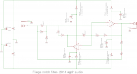
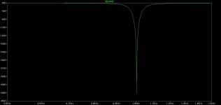
For fun I may try a Fliege notch filter. This fellow
Notch Filter Calculator
may have a point about the Fliege being a little more real-world component friendly than a Twin T since it is mainly resistors. For the one capacitor value I've found a 1% polypropelene at Mouser.
The layout is 4 layer. top = routing, next = ground, next = Vcc, bottom = Vee.
Attachments


Last edited:
Thanks -- the Fliege looks to me like it requires fairly careful capacitor matching. I'd love to see tuning vs. component sensitivities and to know noise and THD from a real circuit. The Bainter filter also offers some advantages re components. Someday I'll get back around to looking at these.
Yeah, I'll be quite curious how it actually performs. Looks like there is such a thing as a 1% 50V COG MLCC 1206 SMD these days. 81-GRM31M5C1H473FA1L at Mouser for $1.29. Lol - maybe the last 4 digits of the part number being "FAIL" is telling me something upfront. 🙂 I think my caps are going to shrink.
Last edited:
The limitations are in the analog input and the analog to digital computer. if you had an adequately pure sine wave with an optimum phase tweak you could use it to notch/null the incoming sine wave. But Bob's distortion magnifier does this already when you are testing a device in the middle. Its conceivable that a scaled version of the input could be added back but unless its smartly filtered it will attenuate everything by 20 dB. If it is filtered then the can of worms is the filter and its associated damage, after you get the amplitude/phase right. I think a passive notch filter (like the B&K) with a controlled depth (-40dB) (more difficult than it first seems) with a preamp on its output set to +40 dB would be ideal.
For those interested in this approach --> See B&K 1607 subject here at DIYAudio - Equip-Tools. (pg 6, now)
Thx-RNMarsh
Thx-RNMarsh
I think a passive notch filter (like the B&K) with a controlled depth (-40dB) (more difficult than it first seems) with a preamp on its output set to +40 dB would be ideal.
How about the approach to modify a tuned notch: instead of tuning it to minimum output, tune it to output at 1/100 of fundamental amplitude?
Should require only some modification in the control references, not the concept as such.
You would make sure it remains detuned at 1/100 of fundamental output.
Jan
For those interested in this approach --> See B&K 1607 subject here at DIYAudio - Equip-Tools. (pg 6, now)
Thx-RNMarsh
http://www.diyaudio.com/forums/equipment-tools/239923-b-k-1607-notch-filter-activated-1.html
Dan.
Maybe a Bainter notch...
@Demian -- The Bainter notch filter's depth is controlled by the gain of an amplifier, so it may be perfect for a notch with controlled depth -- I would prefer 60dB rather than 40dB. I'm attaching a paper by Bainter that davada sent me.
@Demian -- The Bainter notch filter's depth is controlled by the gain of an amplifier, so it may be perfect for a notch with controlled depth -- I would prefer 60dB rather than 40dB. I'm attaching a paper by Bainter that davada sent me.
Attachments
There are some practical issues around a 60 dB notch with 60 dB of gain afterwards. If you have hum it could overload the next stage or at least confuse auto notch stuff. 60 dB of notch would require pretty careful tuning. If its auto-null you are back in the same turf. If its manual its hard to get there with a notch that doesn't screw-up the second harmonic. Stability of both a generator and a notch at that level is also an issue. The targets for a device like this would be analyzers that already have 100 dB THD+N capability I would think, so an extra 40 dB is really at or past the SOTA today.
I think it would want a really good differential amp in front of the notch as well to be useful.
I think it would want a really good differential amp in front of the notch as well to be useful.
Hey Davada,
tried to send you a message, but you're full up.
Alan
It's empty now.
There are some practical issues around a 60 dB notch with 60 dB of gain afterwards. If you have hum it could overload the next stage or at least confuse auto notch stuff. 60 dB of notch would require pretty careful tuning. If its auto-null you are back in the same turf. If its manual its hard to get there with a notch that doesn't screw-up the second harmonic. Stability of both a generator and a notch at that level is also an issue. The targets for a device like this would be analyzers that already have 100 dB THD+N capability I would think, so an extra 40 dB is really at or past the SOTA today.
I think it would want a really good differential amp in front of the notch as well to be useful.
I have no trouble tuning a -60dB notch with Dick's design. It tunes easily and will stay at -60db for an hour if the box isn't jarred. Can't say the same for -80db and -100db. Why is it so important to add gain equal to the notch depth. With no added gain one simply divides the FFT THD percent reading by 1000 for -60dB notch. If it desirable to add gain, add something reasonable like 20dB and then calibrate the software with a -20dB input. The software will indicate the correct level. This can be done in the QA400 by using the extra gain feature.
If you are using a conventional distortion analyzer you need a minimum signal to lock to. Some software would. Also need it.
Sent from my MyTouch 4G Slide using Tapatalk
Sent from my MyTouch 4G Slide using Tapatalk
Just in case there's any question about disseminating an article from a copyrighted magazine, your document may have originated on Mr. Bainter's own web page: http://bainter.org/howto/Active-Notch-Filter-(Bainter).pdf@Demian -- The Bainter notch filter's depth is controlled by the gain of an amplifier, so it may be perfect for a notch with controlled depth -- I would prefer 60dB rather than 40dB. I'm attaching a paper by Bainter that davada sent me.
He also uses the circuit as an instructional example of how to write node equations for circuit analysis. See "How to Write Node Equations for Active Circuits" at http://www.bainter.org/howto/How-to-Write-Node-Equations-for-Active-Circuits.html
That exercise and discussion provide some more insight into how the circuit works.
Analog Devices has a Mini-Tutorial (MT-203) that outlines a design approach:
http://www.analog.com/static/imported-files/tutorials/MT-203.pdf
The original article says the main opamp should have an open-loop gain of 10,000 V/V (10^4; 80 dB) at the notch frequency for good performance. Based on that rule-of-thumb, a notch at 20 KHz requires an amplifier GBW of 200 MHz. While there ARE readily available opamps meeting that criteria, IC's that are commonly favored for high-performance audio applications (low noise, low distortion, etc) tend to be in the 10 MHz - 50 MHz range. Even the AD797 and LME49990 fall short by an octave or so.60dB gets my vote also.... assuming you can hold that at highest freq.
Is there a composite opamp that could be applied here? It should offer the necessary GBW within the audio band of interest. At the same time it shouldn't negate the extension of measurement range (to -120 dBc; -130 dBc; or whatever is desired) by corrupting the signal being notched as it passes through.
Dale
While "lock to" isn't a very precise technical term, your meaning is quite clear: the output of whatever mechanism is used to remove the fundamental signal (notch filter, phase cancellation, etc) must still contain enough residual from the fundamental to derive tuning information. This seems like a basic philosophical flaw in the instrument's architecture.If you are using a conventional distortion analyzer you need a minimum signal to lock to. Some software would. Also need it.
Rather than adding an independent, stand-alone, notch filter before - or after - the circuit that removes the fundamental, is there some two-stage architecture that provides a practical way to couple tuning information from one stage to another? I'm thinking of a first stage that provides a moderate degree of fundamental removal - say, 40 or 60 db - but leaves enough residual that an auto-tune capability can be implemented using feedback methods. Then, the auto-tuning information is fed-forward to tune the second stage to achieve additional fundamental removal without the requirement for a residual fundamental signal at the second-stage output.
Dale
While "lock to" isn't a very precise technical term, your meaning is quite clear: the output of whatever mechanism is used to remove the fundamental signal (notch filter, phase cancellation, etc) must still contain enough residual from the fundamental to derive tuning information. This seems like a basic philosophical flaw in the instrument's architecture.
Dale
If you send a residual with the fundamental suppressed to the QA400, it 'locks' on to the first harmonic that it sees and indicates that with the highlighted 'F' for fundamental.
I did this with a 1kHz notched signal and the QA400 showed the 2nd as F.
But this still requires some reference to the original fundamental amplitude, of course.
Jan
- Home
- Design & Build
- Equipment & Tools
- QuantAsylum QA400 and QA401