Slightly OT: Matt, great article on Quantasylum in the March AudioXpress issue. Now I know how your face looks ;-)
Jan
Jan
I have written Matt about some questions i have about the QA401 (or QA402) for my purposes.
Maybe good to display it here so someone with the same questions can look it up here instead emailing Matt (think he's busy enough).
Because my HP3561A broke down i was looking for a fix it or a newer replacement analyzer with same specs.
I mainly will use it for testing power supplies used for audio equipment based on LDO's 3042/45, TPS7Axxx etc on ripple and noise (which is also a challenge for the HP) and to see if my dc cables will or will not pick up 50Hz main noise.
Because of the LDO's very low ripple/noise the combo QA401/QA471 will do the trick because of the 30dB external gain it will measure noise down to -125 dBV (20 to 20K, no weighting).
I had some questions about the AC Coupler of the QA471.
There could be a momentary flow of current when you connect a voltage source.
So when i want to measure my power supplies (DUT) i first connect them on the 30dB input of the QA471 and switch the DUT to "on" before i connect the 30dB output to the QA401/2.
1) Is this the 'safe' method so i can measure my power supplies ?
2) Can i measure power supplies with different loads and connect it to the QA471 (parallel) or is it only aloowed to connect without a load?
1) Is this the 'safe' method so i can measure my power supplies ?
2) Can i measure power supplies with different loads and connect it to the QA471 (parallel) or is it only aloowed to connect without a load?
I use a pair of diode conducted low noise transistors to drain the capacitor. There's a pin-jack that I can insert a DMM probe to see if the DC level is low milliVolts.
There is/was a good thread on input protection. See also "The Art of Electronics, The X Chapters" for a nice description of the protection scheme for the HP (now Keysight) 34401 DMM.
The AX article was really great! You also get a picture of SY
One of Jack's measurement preamps using an SSM2019 is plenty good enough for measuring power supply noise. He's probably too modest to point that out.
https://linearaudio.nl/sites/linearaudio.net/files/v4 jdw.pdf
Replacing the 600 Ohm resistor at the output with close to 50 Ohms would also let you use a tinySA more effectively for noise readings out to almost a MHz, depending on the gain you use with the SSM2019.
https://linearaudio.nl/sites/linearaudio.net/files/v4 jdw.pdf
Replacing the 600 Ohm resistor at the output with close to 50 Ohms would also let you use a tinySA more effectively for noise readings out to almost a MHz, depending on the gain you use with the SSM2019.
Don't spend too much time on this topic. Ripple and noise in the power supply for audio are overestimated. A well-designed audio circuit will completely suppress noise from vcc. An LM317 is sufficient here.
So, you cheated? I can't think of a better place to take great ideas from!CG -- please give credit to Walt!
But, I see that power supply noise and all that stuff doesn't matter, so there's no point to continue on this discussion...
I had some questions about the AC Coupler of the QA471.
There could be a momentary flow of current when you connect a voltage source.
All i want to know if i can connect safely a dc voltage with load (parallel measurement) to the QA471 at the 30dB input without destroying it.
Before i buying the combo and it turned out i can't use it.
Got an email from Matt with confirmation that it will work.All i want to know if i can connect safely a dc voltage with load (parallel measurement) to the QA471 at the 30dB input without destroying it.
Before i buying the combo and it turned out i can't use it.
So for LDO measurements i will buy the QA401 or 402 (can't decide yet) with the QA471 because of the 30dB pre amp.
I'm new to QA401, just tried it for the first time.
Posted my observations in here.
The basic problem I see is the noise floor at -100dB.
Any hints what might be the problem?
QA401 was connected to desktop PC, powered by the same mains as the amp.
Perhaps it's better to run it from the battery powered laptop?
Posted my observations in here.
The basic problem I see is the noise floor at -100dB.
Any hints what might be the problem?
QA401 was connected to desktop PC, powered by the same mains as the amp.
Perhaps it's better to run it from the battery powered laptop?
Last edited:
Need more info on your measurement setup. Differential or single ended? 48k or 192k sampling? Number of points resolution?
Have you tried a loopback self test as an initial baseline? It's described in the setup directions I think.
It is important to have enough power for the QA401. Make sure you have a good usb cable with substantial power conductors. An external powered hub can help. The QA401 is already well isolated, you should not need laptop on battery.
The load is build from: 4 Ohm + 0.82 Ohm + 4 Ohm (-20.6 dB).
Signal is tapped from 0.82 Ohm, and fed to QA401 as a differential signal
(Input +L and -L, shield of BNCs is not used)
Generator output is taken from +L BNC connector (shield + signal) and fed to the amp's input. Amp doesn't have volume knob.
I didn't try the loopback self test. I followed instructions from "Basic: Power Amps" pdf document from QA's website.
I guess I should do try it.
Are you measuring a bridge tied amp? Having the .82 in the middle is best for a BTL amp. It should be on the ground end for a single ended amp. I have been getting great results from the cheap china wirewound load resistors 50/100W 0.01-50 Ohm Watt Shell Power Aluminum Housed Case Wirewound Resistor | eBay they actually measure almost no inductance to 150 KHz. They do need a serious heat sink if you are running them hard. Old trick- dump them into a small bucket of water. They won't get above 100C until the water boils off.
In any case first turn off the attenuator in the QA401. You do not need it with the 20 dB from the load resistor. Second, increase the fft to 64K. These will get you at least 23 dB lower visual noise floor.
Also, are you using shielded cable to the input of the QA401? Those connection could pick up a lot of common mode noise if not shielded.
If I ground both inputs (L+ and L-), noise floor seems to be at -127dBV.
Slightly better. How come I see screenshots online with noise floor at -140dB ?
Update: I see, if I change settings for dbV, and set input gain to 0 (instead of -20.6), the noise floor I'm seeing now is -150 dB
Also tried with laptop running on battery, and with powered usb hub. No difference whatsoever..
So simple question: to test non-bridged amp, 1 channel, up to 100W RMS, what load should I use?
8 Ohm + 0.82 Ohm will be fine?
So ground from the output of the amp should go to L- input, and output signal (taken from 0.82 Ohm resistor) to L+ ?
How to change FFT to 64k ? I searched for this option, nowhere to be found...
Last edited:
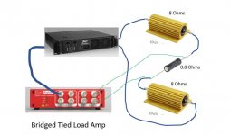
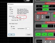
There are arrows above "fft" that control the fft resolution. Ill post a sketch and explain the connections so it makes sense I hope.
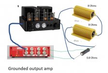
I hope these help. The show the connections for a BTL amp (what you are doing now) a grounded amp and the setting windows and where the FFT settings are.
You want to keep the voltages at the .8 Ohm resistor as small as possible to reduce common mode errors. On a grounded amp one output stays at ground so the .8 Ohm resistor connects there. For a bridged amp both outputs swing opposite each other so you want the resistor in the middle where the swing is minimized.
You also want to add the external attenuation in the dBV menu shown to correct for the external attenuation. Right click on the dBV button to get the dBV menu.
Let me know if you need more clarification.
Attachments
Thanks a lot Demian! It helps a lot!
My dummy load is built like for bridged amp. Need to build another one for grounded amp.
My dummy load is built like for bridged amp. Need to build another one for grounded amp.
Last edited:
Sorry to interrupt.
I am interested in taking IMD measurements of amplifiers I build and while I have function generator and oscilloscope experience, anything beyond that would be new to me.
I was looking at augmenting by bench setup with the veritable HP339A for use with my Rigol DS1054 but upon further research discovered the HP339A is a bit of a boat anchor these days and that I should be looking at the QA units instead.
So my question is, are there resources available for a dummy like me to use the QA device so that I can use my existing scope to see IMD sideband distortion graphically?
Sorry for the newb question.
TiA
- Home
- Design & Build
- Equipment & Tools
- QuantAsylum QA400 and QA401