He tested CFL lamps not LED lamps.
This was a good few years ago IIRC - before LED lamps were on general sale.
This was a good few years ago IIRC - before LED lamps were on general sale.
Common Mode Rejection
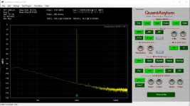
Finalizing my passive lowpass input filters I had a second look at CMRR of the QA401.
Test setup:
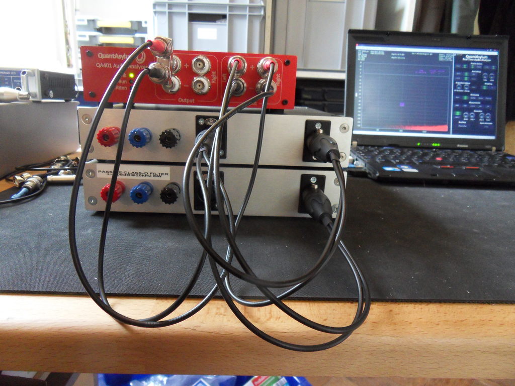
Results: (Only the left channel is sweepable in the QA application, so I had to tune in each value manually.)
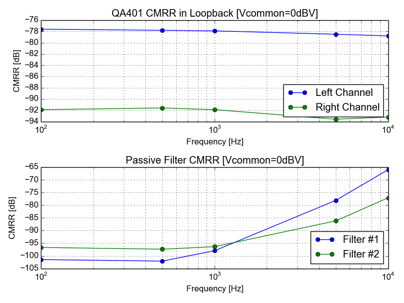
Obviously the right channel of my QA401 has a much better Common Mode Rejection. I will have to send some more time on the trimming of the filters.
Finalizing my passive lowpass input filters I had a second look at CMRR of the QA401.
Test setup:
Results: (Only the left channel is sweepable in the QA application, so I had to tune in each value manually.)
Obviously the right channel of my QA401 has a much better Common Mode Rejection. I will have to send some more time on the trimming of the filters.
Attachments
I just tested a Utilitech Pro 75W equivalent (12W) Led lamp, I measured a PF of 0.98.. So what modern lamp was he testing? This is typical of the led lamps I have all over the house.
Florescent lamps. The screw in ones.
LEDs are different story.
Makes sense, I've tested some of those too, not very good. The supply that came with my Dell laptop has a PF of 0.55 too which is not very good, but my new (and not inexpensive) HP Elitebook's supply managed 0.39 - truly bad, apparently no PF correction.
Low power stuff gets something of a pass on PF but still has some harmonic stuff to deal with on CE standards. Also at low power some instruments are not good at measuring PF.
David, 1966 actually. And can we say "Thank You" Kaiser Aluminum!How old is your house. Old enough to have aluminum wire?
That stuff will hum and buzz with incandescent lamps never mind florescent.
At least it's a pier and beam foundation. Nothing quite like
a concrete slab in the clay of Texas. I'm down to the bed rock,
though gradually moving down hill.
I'm putting it on my list of things to do.
Yes, I've done much tightening to the ELE outlets
and switches along with replacements over the years.
Cheers,
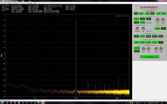
I need to take some accurate measurements of the output of a power amplifier I built. I used a differential to single ended interface using an op amp (TL082), in front of the input of my Q400 distortion analyzer.
So I put in a loop to see what the distortion was at the output of opamp at 6V. I used a voltage divider at the output and the op amp circuit has a gain of 12 V/V. My issue is that the typical THD for the TL082 is 0.003% at 6V out, from it's spec sheet, yet I get much lower distortion. I calibrated the Q400 per instructions some time ago. Just wondering if I can trust these distortion measurements? Anyone know if the TL082 can measure this low? Or does it indicate a problem with the Q400? Maybe needs to be recalibrated?
So I put in a loop to see what the distortion was at the output of opamp at 6V. I used a voltage divider at the output and the op amp circuit has a gain of 12 V/V. My issue is that the typical THD for the TL082 is 0.003% at 6V out, from it's spec sheet, yet I get much lower distortion. I calibrated the Q400 per instructions some time ago. Just wondering if I can trust these distortion measurements? Anyone know if the TL082 can measure this low? Or does it indicate a problem with the Q400? Maybe needs to be recalibrated?
Attachments
The measurements look valid and are what you can get from a QA401. The TL072 is much better than its spec sheet. The specs were written in the late 1970's originally I think. .003% was SOTA and really at the limits of contemporary test systems then. Once specified you don't change specs or you may have problems with customers who need exact equivalents.
John, you could alter your TL082/TL072 distortion test circuit, so that it has continuously variable amounts of distortion. For example, you could modify the voltage divider on the opamp output.
You could connect (a 1 Megohm potentiometer, in series with an 1N4148 diode) in parallel with the top resistor in the voltage divider. When R=1Meg, distortion is minimal. When R=zero, distortion is huge.
Try it and see whether this gives you confidence in the QA401, or whether it confirms your suspicions that something is very wrong.
Thanks Mark, I think it is okay. I've taken distortion measurements of a number of circuits with it and the Q400 shows the distortion spectrum well, at different voltage levels too. Just thought there might possibly be a calibration issue, but given 1Audio's comments it is most likely fine.
If you're here it's unlikely you're working in any physics field where that may even remotely be a consideration...
#justsaying

#justsaying
I have a question : there is a nonmagnetic bnc-rca adapter for QA401 ?
5227699-1 TE Connectivity AMP Connectors | Connectors, Interconnects | DigiKey
Thank you very much. The BNC female connectors of the QA401 are nonmagnetic but all BNC-RCA adapters (3 different models) which I test it have magnetic body. I am trying to find a nonmagnetic body for BNC(male) to RCA(female) adapter.
Newbie question about QA401..
I just ordered a QA401 last week. I had a look at the PDF user's manual and could not find any quotes about how to save or load the displayed curves on the screen.. THD, FReq response, ex..
Can the program do so ? Then how.
Thanks
I just ordered a QA401 last week. I had a look at the PDF user's manual and could not find any quotes about how to save or load the displayed curves on the screen.. THD, FReq response, ex..
Can the program do so ? Then how.
Thanks
- Home
- Design & Build
- Equipment & Tools
- QuantAsylum QA400 and QA401