Just checked and the input Z is 100K up to about 50 KHz. at 100 KHz its about 50K (from shunt capacitance). A suitable 10X (-20 dB) probe would be a 990K resistor with (guess) about 30 pF in parallel with the resistor. If you use a 976K resistor with a 20K pot in series you can trim the two probes for CMR and should be able to get 40 or maybe 60 dB CMR.
I was mistaken about the max input. Its 20V. Keep in mind its not been tested for safety with higher voltages so be careful. Don't hang a probe on the plate of an output tube unless you really know what you are doing.
I was mistaken about the max input. Its 20V. Keep in mind its not been tested for safety with higher voltages so be careful. Don't hang a probe on the plate of an output tube unless you really know what you are doing.
OK, thank you very much for your comments. The Idea behind this schematic was:
#0 Banana jacks
#1 HF-LPF at the input
#2 Switchable 10dB in order to achieve -10/-20/-30dB attenuation for the QA401
#3 standard 0207/THT precision metal film are easiest to source for me, restriction to E12-sereis. Input Impedance as low as possible, for noise - but power disspation in the divider network is not negilible...
On Top, CMRR will depend on matching of the divider network, hence the 0.1%.
#4 cut-off frequency above 100kHz and preferably no impact on phase response below 20kHz
#5 Input Protection. I am not very happy with the zener-diode arrangement since it will add some distortion to the signal under investigation. But until now I did not come up with something better whilst keeping its simplicity.
The alternative to individual resistors:
http://www.mouser.com/ds/2/427/orndivid-239993.pdf
what about a transdiode for 0.7Vdc limiting?
They will start to turn on @ ~0.4Vdc
Stacked/series connected voltage limiters will reduce the parasitic capacitance. I suspect this capacitance is the major contributor to distortion prior to the limiting action.
A transdiode+Zener will very significantly reduce capacitance.
Some are using D+S to Gate of a low gm jFET as a limiter.
Again this could be series connected to a higher voltage limiter.
It's probably a transdiode that is used to protect the inputs of many ICs.
yes, you see it in a few simplified IC sch.
Have a look at FREX limiter. It is jFET tied into supply rails. Limits the input to 0.6V outside the supplies. But you could set a voltage sink at lower than supply rails and tie the jFET to that lower rail to set a lower limiting voltage.
Remember the input resistor sets the source impedance that prevents the limiter blowing up. And that protecting R increases input noise.
OK, thank you very much for your comments. The Idea behind this schematic was:
#0 Banana jacks
#1 HF-LPF at the input
#2 Switchable 10dB in order to achieve -10/-20/-30dB attenuation for the QA401
#3 standard 0207/THT precision metal film are easiest to source for me, restriction to E12-sereis. Input Impedance as low as possible, for noise - but power disspation in the divider network is not negilible...
On Top, CMRR will depend on matching of the divider network, hence the 0.1%.
#4 cut-off frequency above 100kHz and preferably no impact on phase response below 20kHz
#5 Input Protection. I am not very happy with the zener-diode arrangement since it will add some distortion to the signal under investigation. But until now I did not come up with something better whilst keeping its simplicity.
The alternative to individual resistors:
http://www.mouser.com/ds/2/427/orndivid-239993.pdf
The integrated dividers are a good idea however the voltage is limited to 100V and the power is limited.
The input protection in the QA401 is not introducing distortion. Its very similar to what is in most audio analyzers. Adding more protection may not help much. The reversed biased diodes do work well. You do need some current limiting to protect the diodes. This all becomes clear in the complete schematic. 100V 3W light bulbs are the best solution I have seen. Low off resistance for low noise and higher on resistance to limit the current. However if you have a voltage divider the series resistance will accomplish all the current limiting you need.
The low input impedance of your network will interact with sources and devices. 10K is the minimum IHF expected an audio product to drive. Even in professional applications 600 Ohms is almost never used since its seen as just wasting signal and SNR unnecessarily. Most audio analyzer have 100K input (or 200 K differential). Most measuring instruments are higher since the loading alters the levels and degrades the accuracy.
10 dB steps are not well suited to this system since its really more decimal based. If you knock the input down by 10 dB rescaling is quite involved. 20 dB is easy.
If you convert to banana jacks you still need adapters to talk to audio connections (RCA, XLR) and in any case you will need a load resistor for power amps.
Even with .1% resistors various errors still add so a trim for CMRR is still necessary. You just need one. The .1% resistors won't be .1% over time and all the other things that affect them. This can be a very unpleasant lesson to new engineers working on instrumentation. A trimmer for R and a trim for C goes a long way.
The divider network is an issue for noise on higher voltage signals. But incorporating it into a load resistor eliminates those issues. I would use a 99 Ohm resistor and a 10 Ohm resistor for that in parallel with the load resistor or a speaker. Much easier and the divider won't contribute any noise to the measurement. .1% 5W resistors are not a practical option so you will need trimmers BUT the low impedance is far less sensitive to stray impedances.
I'm thinking about incorporating all these ideas in a selector box kind of like an ST 1200 without all the extra stuff that is way obsolete today. http://www.cieri.net/Documenti/Misu...gy - Stereo Test Panel model 1200A (1978).pdf
Couldnt open the pdf on my phone. Using a fet as a series switch is problematic if there is any gate modulation. The light bulbs will easily handle 100V and are like 1k or less off. A Fet canbe 10 Ohms on but you need to keep it on through the complete cycle. Ill try to get the pdf when next at a pc. I can envision some schemes for making a fet work.
Sent from my LG-H811 using Tapatalk
Sent from my LG-H811 using Tapatalk
Couldnt open the pdf on my phone.
Maybe this will help:
Nut's, just don't look at the name.
Attachments

Very interesting trick. I just tried a simulation using LSK389 (closest in my database to a J110, which is what I would use). Attached is a simulation I just tried. With a 100K source I get about -96 dB for HD3 which is not bad. That would be the effect of the cap modulation in the reversed biased diodes.
I'll look into breadboarding it and trying it in something, but not for a while. I'm really busy until CES is over. Maybe someone else is interested?
I tried simulating with depletion mode Mosfets and LTSpice crashed hard.
I'll look into breadboarding it and trying it in something, but not for a while. I'm really busy until CES is over. Maybe someone else is interested?
I tried simulating with depletion mode Mosfets and LTSpice crashed hard.
Attachments
Tell LTSpice that. . . I'm sure it would work. Not sure if there would be any nonlinearities. However a quick breadboard would answer all. The Mosfets would get 400V out of the circuit which would be very attractive.
Very interesting trick. I just tried a simulation using LSK389 (closest in my database to a J110, which is what I would use). Attached is a simulation I just tried. With a 100K source I get about -96 dB for HD3 which is not bad. That would be the effect of the cap modulation in the reversed biased diodes.
I'll look into breadboarding it and trying it in something, but not for a while. I'm really busy until CES is over. Maybe someone else is interested?
I tried simulating with depletion mode Mosfets and LTSpice crashed hard.
It ran for me using depletion mosfets but it was ugly.
Lamps don't distort until the frequency gets low. Like 10Hz.
Even at 10 Hz with microamps through the filament its not going to affect the distortion. The Jfets looked promising. it would be a simple breadboard. Just no time for now.
With "transdiode" you refer to a BE-shorted BJT?
I like the Idea of the series-Connection 🙂
I think a transdiode is a transistor with the input signal connected to the emitter, the base connected to a reference voltage (often ground), and the collector connected in such a way that its current, which appears essentially as the signal current when the signal is sufficiently negative (for NPN), is used in some way, often as part of a limiting circuit. As such, it is not the same as a diode-connected BJT where the diode function is implemented with the CB junction. The transdiode is often found in a logarithmic amplifier, where it implements the feedback path around an op amp in the inverting configuration.
When just using a BJT with BE shorted to form a diode, it is important to recognize that the reverse breakdown of the diode formed is often only on the order of perhaps 4V; so it acts as a Zener diode. BTW, reverse BE conduction (breakdown) in a BJT will usually degrade the transistor over time, resulting in a reduction of its beta. Of course, in some applications this may not matter.
I have not tried it, but a JFET with drain-source shorted together can also be used as a diode, and it will typically have a significantly higher reverse breakdown. The capacitance of the gate-channel junction formed may, however, have significant capacitance, especially for large-area low-noise JFETs like the LSK389. The LSK489 has substantially less capacitance.
Another reasonable approach is the 1N4149, which has lower capacitance than the 1N4148.
Cheers,
Bob
All very interesting stuff to explore. For me mid January but maybe someone else can give it a try sooner.
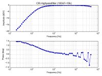
Hello again, the attenuator-project is still ongoing but currently I am quite busy exploring all the features of the QA401. Just now I did a test of the stepped-frequency response plugin. Somehow the phase-information seems to be lost.
Actually, looking at the phase-display in the upper right corner of the qa401-application-window during the sweep, the displayed figures seem to be correct BUT the exported .csv is definitely wrong. See plot below. Has anyone ever tried and got the same results?
The Visual-Studio stuff is still installing (since 3hrs now 😡)... anyways, I attempt to write my own script to overcome this issue.
Attachments
Hello again, the attenuator-project is still ongoing but currently I am quite busy exploring all the features of the QA401. Just now I did a test of the stepped-frequency response plugin. Somehow the phase-information seems to be lost.
Actually, looking at the phase-display in the upper right corner of the qa401-application-window during the sweep, the displayed figures seem to be correct BUT the exported .csv is definitely wrong. See plot below. Has anyone ever tried and got the same results?
The Visual-Studio stuff is still installing (since 3hrs now 😡)... anyways, I attempt to write my own script to overcome this issue.
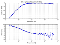
The magnitude response seems spot on.
Maybe the phase is in radians rather than degrees? Then it would also seem to be OK.
Jan
Hello Jan, thanks for the input. I did a second measurement to confirm this behaviour and plotted results with rad->deg transformation. Looks like expected and the 45deg crossing point is around 184Hz, these results look promising but I am still a little bit suspicious.
I guess the huge spread above 10kHz is due to general inaccuracy around 0deg?
I guess the huge spread above 10kHz is due to general inaccuracy around 0deg?
Attachments
Last edited:
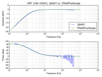
Jan you were absolutely right - spot on 😉
Here is an overlay of two measurements. One is done via QA401 with 0dBV an 10points per octave between 20Hz and 48kHz. The second was captured with the very same circuit, wiring etc. Despite the fact that a PicoScope (15bit resolution) was used with 25points per decade between 10Hz and 100kHz, level was 1V.
Here is an overlay of two measurements. One is done via QA401 with 0dBV an 10points per octave between 20Hz and 48kHz. The second was captured with the very same circuit, wiring etc. Despite the fact that a PicoScope (15bit resolution) was used with 25points per decade between 10Hz and 100kHz, level was 1V.
Attachments
- Home
- Design & Build
- Equipment & Tools
- QuantAsylum QA400 and QA401