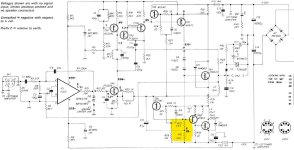
A voltage-output VAS adds clarity but is not essential. A voltage-output VAS with the gain of 1000 in series with a 100ohm resistor can be replaced by its Norton equivalent: a current-output VAS with the transconductance of 10, loaded by the same 100 ohm resistor. The nulling principle remains the same. If you replace E2 in your simulation with a voltage dependent current source G with the value of 10, you'll get a nice null, too.
BTW my post #58 above mistakenly shows that the left end of the 2-ohm resistor R3 of the nulling network is connected to the output of "OPS" and not to the output of "VAS"; sorry about that. With a voltage-output VAS it makes no difference for the results of the simulation - that's why I didn't notice it until it was too late to correct. It does make all the difference with a current-output VAS though.
BTW my post #58 above mistakenly shows that the left end of the 2-ohm resistor R3 of the nulling network is connected to the output of "OPS" and not to the output of "VAS"; sorry about that. With a voltage-output VAS it makes no difference for the results of the simulation - that's why I didn't notice it until it was too late to correct. It does make all the difference with a current-output VAS though.
Last edited:

Note: I am posting this as I have a related question on the Class-A output stage (plus two other questions). If this should be in a separate thread, kindly remove my post and let me know.
I have a few questions on the Quad 405 that I am struggling to understand and that I can't find answers to. I have built two Chinese Quad 405 clones (LJM), of a Quad 405-1 revision. I have implemented some of Keith Snook's and Bernd Ludwig's suggested modifications. Some of which were successful (e.g. the non-inverting Opamp configuration lowers the noise) others not so (the 'ring of two' class-A output stage with the feedback capacitor C8 returning to the emitter of Tr2 not being HF stable). I have limited means to measure absolute distortion figures (PicoScope 2000), so with some modifications, I have to rely on what others have tested and published. I am also looking at the subsequent Quad 306 and 606 to see if there are any other modifications that could be beneficial to the 405.
My questions are the following:
- Walker's papers show a current source for the class-A driver of 50 mA. In the 405 these are resistors R30/31 setting the current to 50 V / 2 x 0.56 k = 45 mA. The closest you can get to 50 mA with the E-12 series. Fair enough. In the 306, these resistors are kept at 560 Ohm, while the supply voltage is lowered to -38 V, lowering the current to 34 mA. I am planning to run my "Quad's 405" on + and -42 V. Is there any benefit in lowering R30/R31 to 470 Ohm, as this would bring the current back up to around 45 mA?
- Snook shows a base stopper resistor of 10 Ohm for upper dumper Tr9. Quad introduced this in the 606 where there are triple dumpers (R7 in the 606 schematic). I suppose to promote better stability. However, for a single transistor output, 10 Ohm seems much too high to me as a single TO-3 output transistor suffers from significant beta-droop at higher currents. Wouldn't 2R2 be more sensible, if at all necessary?
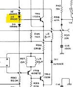
- In the 306/606 and further revisions, Quad introduced another diode in the dumper section (D7 in the 606, D8 in the 306). It anti-connects the base/emitter of the upper dumper(s) (Tr9/10/11). What is the purpose of this diode. Would there be any benefit in implementing this in a 405?
Attachments
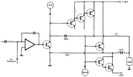
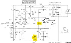

The diode protects the emitter junction from excessive reverse voltage. The base-emitter reverse breakdown voltage is low, typically 5V, and can easily be exceeded e.g. in case of clipping or shorted output.Quad introduced another diode in the dumper section
Thank you for your answer. Pardon my ignorance, but would you know why it was only added to the upper dumper, and not the lower one?The diode protects the emitter junction from excessive reverse voltage. The base-emitter reverse breakdown voltage is low, typically 5V, and can easily be exceeded e.g. in case of clipping or shorted output.
Last edited:
It was added between them, not to either one or the other of themThank you for your answer. Pardon my ignorance, but would you know why it was only added to the upper dumper, and not the lower one?
And I have no belief in the protection theory advanced here. The Quad documents state that it was added to ‘correct the response at 20kHz’.
@ejp you are right about the extra diode to reduce the dead zone (D15 in the 405-2 schematic). My question was on D6 in the 306 schematic. Since I have never seen such a flyback diode on an emitter/base junction, I think I will not implement this.
As for my first question, I will test the amplifier at both 50 V and 42 V, with and without altering the current source R30/31 for the 42 V supply, and try to check for differences in harmonic distortion.
For my second question, I will not go with a base stopper for the upper dumper unless I see HF instabilities, and then I will max. it at 2R2.
Thank-you all for your help.
Attachments
Well guys, welcome or not - I'm back!
Fascinating stuff, thankyou all, just brilliant discussion.
I am at a loss however, to pursue any of this without test facilities. Since Jan commented that perhaps I should get a good class A Can amp, I have started using my Sugden Headmaster with as pair of HIFIMAN Planars. Quite superb! I can't however judge the 909 fairly against it, given I can only drive my Stax' Electrostatics with the 909 and in fairness, the HIFIMANS are probably a lot better than my 52 year old Stax.
However, Mooly's plots (Page2) are very convincing. If my Headmaster performs anywhere near as good, then perhaps it is that which accounts for the difference; more than the difference between the HIFIMANS and the Stax..
I am not ready to give up on my 909 yet though and it is frustrating not to be able to conduct more tests such that what has been posted can sink in. I am juggling a few balls, restoring my 3.0 GTV, preparing the house for sale and trying to find out what has failed on my Q4 3.2 JTS 159, whilst still trying to rationalize Current Dumping.
In this regard, I need some peace - well for a while at least. Therefore, this is my take on it all - leaving all the Maths to one side.
1. There is no cross-over distortion in the 405, or my 909, simply because the Dumpers are switched off!
2. The power level of the Class A amplifier, around the region where cross - over distortion would exist, is sufficient to to drive the output, before the Dumpers start to conduct. This will be up to when the level is beyond the region where the Dumpers are non - linear.
3. As a rule of thumb, I assume, ''Guestimate the output voltage swing of the class A amplifier to be 2 volts Peak to Peak, to ensure that when the Dumpers do switch on, they are well onto their linear transfer characteristic.
4. Before the Dumpers switch on, there is exists linear feedback, from O/P to I/P on the class A amplifier.
5. When the Dumpers switch on, additional to this feedback is the error detected by the ''Bridge'', which is monitoring; effectively, the difference between the input signal to the Dumpers and their output.
6. Errors are detected twice per hertz; on positive going and negative going excursions.
7. Bandwidth of the amplifier therefore, needs to be at twice the highest fundamental of audio. At 20khz. fundamental, this would mean the amplifier needs a bandwidth of 80Khz. The Quad 909 does indeed have a 80khz. bandwidth.
Error - correction; as I will call it, only needs to be invoked in a very small target region of both the positive and negative going excursion, at a point where each Dumper needs to be alternately switched on, and off; which is when the level exceeds their inherent non-linear region.
8. Narrowing the Target Window, by way of diodes has to be judged accurately as the response time of the ''Bridge'' needs to take into account the reversal of signal polarity and needs sufficient decay time to ensure the error signal remains true to the value of both +/- excursions. - purely theoretical posturing on my behalf.
9. The class A amplifier is operating ''Alone'' in the region where power output is low so the level of constant feedback, which exists prior to the invocation of the Dumpers is sufficient for it to remain stable.
10. The Dumpers, being Common Collectors? - Emitter Followers are low output impedance, but will supplement the class A amplifier's negative feedback, once they are onto their linear transfer characteristic, improving stability and lowering the output impedance further.
11. Thus three forms of feedback exists;
a. Fixed feedback of the class A amplifier, in the absence of Dumper conduction.
b. Fixed feedback of the class A amplifier + error feedback at the transitioning point where the Dumpers start to switch on.
c. Fixed feedback of the class A amplifier + feedback from the dumpers when operating beyond their transition point.
I hope this makes sense, although it circumvents the impressive analysis of those who have contributed to this brilliant thread.
I have recently fitted new drivers to my BC1's - bought in 1996 but never needed until now; playing the 909 at low level, brought a tell tale scratchiness to the music as the voice coil rubbed against the magnet housing. The 909 is superb and it is difficult to justify a Sugden Power Amp, not without an A/B comparison test at least. But it seems I have a pretty good compromise at the moment; the Headmaster and phones, or alternatively, the 909 and BC1's.
Life's not so bad - after all!
Cheers Guys,
Brian.
I believe that seeing it as 'errors being detected' when the dumpers switch on is not useful for understanding.Before the Dumpers switch on, there is exists linear feedback, from O/P to I/P on the class A amplifier.
5. When the Dumpers switch on, additional to this feedback is the error detected by the ''Bridge'', which is monitoring; effectively, the difference between the input signal to the Dumpers and their output.
What happens is whenever a dumper current changes, the feedback factor changes to take that into account. It is a continuous process, there's not really two different situations. There is only one situation and a dumper current that varies from almost-zero to some value; the total feedback factor depends also on the dumper current and this is a continuous process.
For analysis it may be help ful to consider the situation with dumper current = zero and dumper current = xA, but the operation is continuous.
Jan
Just considering your comments, in light of my ''mis - use'' of the term error. It is an error, only insofar as it would not exist if the Dumper current ''Overlaid'' the class A output signal over 360 degrees - i.e. was working fully in class A along with the low power section. But I am struggling to find the words to better describe it.
I need to think again how best to describe what is indeed a continuous process, of which the constituent parts are inseparable. For those ill equipped to perform a mathematical analysis, or as a precursor to understanding the math, I find it helpful to rationalize, by way of the discrete action, of constituent parts, which although cannot be separated from the whole, gives a better understanding of what is going on - whether or not I achieve that is a different matter.
When the current dumpers are in service, this error signal is extremely complex, much more so than the complex nature of the musical composition that it may be processing. For it to be effective, it must also be extremely quick in applying it to the signal at the input to the class A amplifier. Not quick enough, it may be argued, if the Sugden/405 plots supplied by Mooly are compared. They seem to confirm my overriding impression that the crossover point between positive and negative excursions is ''Checked'' and the Dumpers only switch on, when the amplitude of the signal from the class A amplifier, would put the dumpers firmly onto the linear part of their characteristic and when they do switch on, they switch on very quickly indeed - Schmitt Trigger - like, as I analogized earlier.
Because, the feedback signal is playing catch - up, is this the reason for the transients which appear in Mooly's display? Would those transient products disappear, if the bias on the Dumpers was increased to the point where their action became class A? If so, this would tend to support my use of the ''error'' term, as it would indicate they are a response to the Dumpers reaching the Target Level? Upon switching on, the transient would quickly reduce as the class A voltage and the Dumper current overlap each other? Another reason for the 80khz. frequency response/bandwidth of the 909?????
Rightly or wrongly, this leads me to conclude, there must be a 'Transient' element in the composite feedback signal, which, when amplified by the ''Hypothetical'' 30db. gain of the class A amplifier, forces the dumpers to switch or very quickly. Whatever conventional NFB component there may be in the composite feedback to the class A amplifier, would not do the same thing.
I hope there is some logic to what I am suggesting. It is of course pure hypothesis as without test facilities, it can't be anything but!
None the less, it is a fascinating subject, regardless of its age. Mind you, I pre - date it. What a depressing thought. Having known of its existence, all its life and still not understanding it!!!!!!!!!!!!!!!!!!!!
Thanks again for the input.
Brian.
There are no transients in Mooly’s display. It’s an FFT and it shows harmonics, and it’s only a simulation. A real 405 cannot possibly behave like that, as it doesn’t have > 100kHz bandwidth. I’ve never seen a harmonic spectrum like that out of a real 405, and I’ve measured hundreds of them.Because, the feedback signal is playing catch - up, is this the reason for the transients which appear in Mooly's display
Well that's a relief. I was almost persuaded to go out and buy a Sugden Power amp on the basis of those plots - he! he!. Thanks ejp, my bank manager (wife) will be relieved. Is there any chance someone has a ''Real Plot'' of the 405? Or for that matter the 909, which is essentially what I am using at the moment.
However, my understanding - rightly or wrongly, remains unchanged, but very open to persuasion. For the Dumpers to 'Overlay'' the class A section accurately, they must be 'Triggered'' into the on - state very quickly, and at a point where they are well past their non-linear region.
However, my understanding - rightly or wrongly, remains unchanged, but very open to persuasion. For the Dumpers to 'Overlay'' the class A section accurately, they must be 'Triggered'' into the on - state very quickly, and at a point where they are well past their non-linear region.
No. @jan.didden has already covered this. The process is continuous. There is no need for the dumpers to be 'past their non-linear region' (which is itself ill-defined). Whatever the dumpers do to the output signal, the Class A part will correct. That's hos the bridge works.However, my understanding - rightly or wrongly, remains unchanged, but very open to persuasion. For the Dumpers to 'Overlay'' the class A section accurately, they must be 'Triggered'' into the on - state very quickly, and at a point where they are well past their non-linear region.
There is no D15 in any 405 schematic. I was referring to D13.@ejp you are right about the extra diode to reduce the dead zone (D15 in the 405-2 schematic).
D6 in the 306 schematic is in the same position as D6 in all the Quad 405 and 405-2 schematics.My question was on D6 in the 306 schematic.
D6 is not a 'flyback diode' and it is not connected between any emitter/base junction. There are two flyback diodes in the 306, D9 and D10, and they are connected between collector and emitter of T9 and T10. There are no b/e-connected diodes in the 306.Since I have never seen such a flyback diode on an emitter/base junction, I think I will not implement this.
Accuracy please.
Yes, I got that, but still have trouble rationalizing how it actually achieves it. However, as Quad themselves state, when the target level is exceeded, the dumpers switch on. Why bother with a target region if all one needs to do is provide a correction signal, such as Gamma Correction to restore linearity? That being the case, what is the point of calling it Current Dumping when they are on virtually all the time - which of course they aren't?
The composite error signal is complex in the extreme, made up of conventional NFB and the 'Correction signal, from the bridge, itself derived from the dumpers. But someone must be able to quantify what it is and how it performs the ''Magic''? Conventional NFB would take the dumpers away from the target region, so the correction signal must come from outside the Negative feedback loop for it to work.
''A transient from a dumper as it starts to conduct, would be outside that Negative Feedback Loop''.
It appears a very convoluted way of achieving current dumping. Overlaying the dumper output upon the class A signal, when the signal crosses the target threshold seems a whole lot simpler, where the only need for correction would be due to any small phase errors. Any phase error would be wholly dependant upon the turn on delay of the dumper derived error signal x class A amp gain. It's` response time will ultimately determine that!
The term 'error' in feedback systems is an accepted term, that's not the issue. It is generally used to describe the effective signal at the input of the amp, being the difference between the input signal on one input and the feedback signal on the other input. This 'error' is amplified by the full open loop gain of the amp and is normally a very small signal but very distorted.Just considering your comments, in light of my ''mis - use'' of the term error. It is an error, only insofar as it would not exist if the Dumper current ''Overlaid'' the class A output signal over 360 degrees - i.e. was working fully in class A along with the low power section. But I am struggling to find the words to better describe it.
I need to think again how best to describe what is indeed a continuous process, of which the constituent parts are inseparable. For those ill equipped to perform a mathematical analysis, or as a precursor to understanding the math, I find it helpful to rationalize, by way of the discrete action, of constituent parts, which although cannot be separated from the whole, gives a better understanding of what is going on - whether or not I achieve that is a different matter.
When the current dumpers are in service, this error signal is extremely complex, much more so than the complex nature of the musical composition that it may be processing. For it to be effective, it must also be extremely quick in applying it to the signal at the input to the class A amplifier. Not quick enough, it may be argued, if the Sugden/405 plots supplied by Mooly are compared. They seem to confirm my overriding impression that the crossover point between positive and negative excursions is ''Checked'' and the Dumpers only switch on, when the amplitude of the signal from the class A amplifier, would put the dumpers firmly onto the linear part of their characteristic and when they do switch on, they switch on very quickly indeed - Schmitt Trigger - like, as I analogized earlier.
Because, the feedback signal is playing catch - up, is this the reason for the transients which appear in Mooly's display? Would those transient products disappear, if the bias on the Dumpers was increased to the point where their action became class A? If so, this would tend to support my use of the ''error'' term, as it would indicate they are a response to the Dumpers reaching the Target Level? Upon switching on, the transient would quickly reduce as the class A voltage and the Dumper current overlap each other? Another reason for the 80khz. frequency response/bandwidth of the 909?????
Rightly or wrongly, this leads me to conclude, there must be a 'Transient' element in the composite feedback signal, which, when amplified by the ''Hypothetical'' 30db. gain of the class A amplifier, forces the dumpers to switch or very quickly. Whatever conventional NFB component there may be in the composite feedback to the class A amplifier, would not do the same thing.
I hope there is some logic to what I am suggesting. It is of course pure hypothesis as without test facilities, it can't be anything but!
None the less, it is a fascinating subject, regardless of its age. Mind you, I pre - date it. What a depressing thought. Having known of its existence, all its life and still not understanding it!!!!!!!!!!!!!!!!!!!!
Thanks again for the input.
Brian.
But I feel there is still difficulty to understand the continuous operation of any feedback system. The expression 'the feedback signal is playing catch - up' points to that. Nothing is playing catchup, it is a continuous process.
Jan
You are right, it is D13. Typo on my side.There is no D15 in any 405 schematic. I was referring to D13.
You are right. I meant 'D8' highlighted in the schematic.D6 in the 306 schematic is in the same position as D6 in all the Quad 405 and 405-2 schematics.
There is, it's D8. My question was on D8.There are no b/e-connected diodes in the 306.
BTW, I conducted tests running a 405 on +/- 42 VDC with both the class A resistors at the original 560 Ohm and at 470 Ohm at 8 and 4 Ohm loads (including capactive loading) and did not see a difference in harmonic distortion or profile, so I kept these resistors at 560 Ohm. I did have to install a 5 Ohm base stopper in the upper dumper to control oscillations in my set-up.
Attachments
Thanks Jan,
But still there remains the issue surrounding the continuous process - in my mind that is. The continuous process is a consequence of what has gone before. I.e., a reaction to the signal crossing the threshold of the target area. Therefore it is always playing catch - up.
Assuming, time zero - If the amplifier is handling an audio signal below the point at which the Dumpers conduct, the the only feedback is that designed into the Class A amplifier. The output signal therefore is governed by the gain of the amplifier, i.e. input signal x gain. assuming zero phase delay, then the audio is a clean representation of the input, times the gain.
When the audio gain is above the target threshold, the Dumpers switch on, but the control signal has not yet been established. It takes a finite time for that to occur. True, the feedback of the class A amp is still present, but not yet that of the dumpers.
Assume also that the Wein bridge arrangement does not exist and when the dumpers do start to conduct, they add further feedback to the overall loop. Would that not reduce the loop gain and potentially reduce the level of output signal back below the dumper threshold?
In that situation, the class A is not exercising control over the dumpers - or am I missing something? However, following along these lines, there has to be something to prevent that happening. That, I argue, ''there is an element of hysteresis inherent in the design, such that although the dumpers switch on at a given level, they switch off again at a lower level?''
I am writing this and thinking on the hoof so please bear with me. The lower level must still be at a point where the dumpers remain linear. Is this the purpose behind the window and if it is, then the upper level must still be within the power capability of the class A amp.
However, adding the bridging circuit, I would argue, would not have such a dramatic effect upon the amplifier, as a whole. To my way of thinking, only an external signal source, independent of the loop gain of the class A and dumpers can do that! And that, I believe, is the trigger/transient which appears at the input to the bridge element, from the dumper as it starts to conduct.
The bridge may well shape the trigger and yes it is true it is continually moderating - if that is the right word - the feedback, even when the dumpers are switched off (?). But it is, I feel, the initial transient transient from the dumper(s), which establishes the current dumping process.
The transient which occurs when the dumper starts to conduct is short lived as the bridging network feeds the class A amp, which quicky; because of its gain, switches the dumper on at a level which coincides with the class A output signal - adding current to the output voltage of the class A. Speculation - any distortion which occurs at that juncture, will be reduced by the increased feedback from the dumpers, adding to the fixed feedback of the class A amp; after the transient has driven the dumper on.
Beyond time zero, this is a continuous process with the dumper transients, being shaped; my belief, by the bridge and fed to the class A input, along with the feedback proper from the class A amp and that from the now operating dumpers.
Perhaps it is the way my brain is wired, but that is the only way I can see this working. The bridge is rudimentary and indeed it was claimed that component tolerances were unimportant to the design. For it to work otherwise, time constants relating to the dynamic loop gain would be crucial to ensure at the very least they conformed to some factory standard.
Yes, there is no question it is a continuous process. However, I believe the error signal is a combination of conventional feedback from the class A, and the Dumpers, when conducting, upon which is superimposed a trigger - for want of a better word - derived from the transient which occurs when the dumpers start to switch on, and shaped by the bridge network. Indeed, it is only required to provide a ''Trigger pulse'' to switch the dumper on quickly. The point at which they switch off could be pre - set as part of the design.
- Home
- Amplifiers
- Solid State
- QUAD current dumping class A output power?