Thank you Jan!
BTW should the OP or someone else feel this discussion is off-topic here, I respectfully ask the moderation team to move it to a more appropriate place.
Let me start from the "current dumper" a.k.a. output stage, represented here by an ideal voltage follower OPS in series with the source of distortion with the amplitude of 1, or 0dB:


It doesn't matter if it's 1V or 1mV or 1μV, as I will be interested in the attenuation of this distortion, and not the absolute level of it.
Next, let's add an input stage + voltage amplification stage with the combined gain of 1000 (for now, independent of frequency), as well as a 1:10 feedback divider, to build a normal feedback amplifier with the gain of 10:


The feedback reduces the OPS distortion by a factor of (1+Loop Gain). The Loop Gain is 1000/10=100, so the distortion is reduced by a factor of 101, or just below -40dB. (If you are unsure how this works, you can look e.g. at my blog or other places that discuss feedback theory basics.)
In order for feedback to reduce the distortion of the OPS by a factor of 101, the VAS should feed the OPS with "pre-distortion" with the level 100/101 (or-0.086dB) and in the opposte phase:

If we combine the output of the VAS and the output of the OPS in the 1:100 proportion, we get a distortion-free output. (Here, -322dB is as close to negative infinity in dB as LTSpice can get):


This is how Walker's distortion compensation works. Note that the proportion of the OPS to VAS outputs at the load is equal to the amplifier's loop gain. And look, mum, no bridge!
Naturally, you can use appropriately scaled inductors or capacitors for summation:

(If you want to simulate this with inductors, keep in mind that LTSpice adds a default series resistance of 1 milliohm, which messes up the distortion cancellation. If you set the series resistance to zero, the simulation is messed up in a different way.)
The frequency-independent gain assumption above was unrealistic, but it allowed me to show the principle more clearly. I will follow up with another post where the loop gain becomes frequency-dependent.
BTW should the OP or someone else feel this discussion is off-topic here, I respectfully ask the moderation team to move it to a more appropriate place.
Let me start from the "current dumper" a.k.a. output stage, represented here by an ideal voltage follower OPS in series with the source of distortion with the amplitude of 1, or 0dB:
It doesn't matter if it's 1V or 1mV or 1μV, as I will be interested in the attenuation of this distortion, and not the absolute level of it.
Next, let's add an input stage + voltage amplification stage with the combined gain of 1000 (for now, independent of frequency), as well as a 1:10 feedback divider, to build a normal feedback amplifier with the gain of 10:
The feedback reduces the OPS distortion by a factor of (1+Loop Gain). The Loop Gain is 1000/10=100, so the distortion is reduced by a factor of 101, or just below -40dB. (If you are unsure how this works, you can look e.g. at my blog or other places that discuss feedback theory basics.)
In order for feedback to reduce the distortion of the OPS by a factor of 101, the VAS should feed the OPS with "pre-distortion" with the level 100/101 (or-0.086dB) and in the opposte phase:
If we combine the output of the VAS and the output of the OPS in the 1:100 proportion, we get a distortion-free output. (Here, -322dB is as close to negative infinity in dB as LTSpice can get):
This is how Walker's distortion compensation works. Note that the proportion of the OPS to VAS outputs at the load is equal to the amplifier's loop gain. And look, mum, no bridge!
Naturally, you can use appropriately scaled inductors or capacitors for summation:
(If you want to simulate this with inductors, keep in mind that LTSpice adds a default series resistance of 1 milliohm, which messes up the distortion cancellation. If you set the series resistance to zero, the simulation is messed up in a different way.)
The frequency-independent gain assumption above was unrealistic, but it allowed me to show the principle more clearly. I will follow up with another post where the loop gain becomes frequency-dependent.
Last edited:

I think this provides some insight into the operation of the 405
https://nick.desmith.net/Electronics/QUAD_upgrades.html
I am not aware of any other unbiased amplifiers that achieve 0.0025% level from 1W to 95W and from 10Hz to 20kHz, when I measured my clone in the early 80s it measured 0.0018% and with ordinary components, no special matching or adjustment.
https://nick.desmith.net/Electronics/QUAD_upgrades.html
I am not aware of any other unbiased amplifiers that achieve 0.0025% level from 1W to 95W and from 10Hz to 20kHz, when I measured my clone in the early 80s it measured 0.0018% and with ordinary components, no special matching or adjustment.
I too am looking forward to that SIM. However, I have a lot of reading to catch up on.Without a shadow of a doubt. Walker did make the DC loop gain of the Quad high (to obtain a "good virtual ground") and mentions a resistor in parallel with the bridge capacitor, which would compensate for other parts being non-ideal.
Walker's analysis only works, at least precisely, for zero-DC-impedance inductors and infinite-DC-gain, single-pole-compensated amplifiers with the time constant set by the "bridge" capacitance. The insight about the ratio of impedances mimicking the loop gain allows for e.g two-pole-compensated amplifiers, which would not be so easy to incorporate into the "bridge" concept. I will show a (simulated) example, but it will take some time for me to post it.
Still, instead of perfecting the distortion compensation, it may be better to just increase the loop gain, which would take a better care of the current dumper's distortion.
''Still, instead of perfecting the distortion compensation, it may be better to just increase the loop gain, which would take a better care of the current dumper's distortion.'' - a simple, yet succinct observation. Getting back to my analogy, Dumper Distortion would be zero, if in essence they appear transparent. Short of leaving them on all the time - operating in Class A - they need to be switched on extremely quickly. Perhaps my words about the speed of the dumpers were mis - interpreted. Actually, what I mean is the speed at which the error signal is applied to switch them on. And, if the distortion products, detected by the ''Bridge'' and fed to the input stage, is subject to the same gain as the input signal (hypothetical 30db.), their transition time would be very quick indeed.
It is all very complex and I struggle with the idea of balancing the bridge as that presupposes it can achieve balance at all frequencies or level within the audio envelope. Whereas, I can envisage, the error signal, not being the product of bridge balance, but simply the sharp transients which occur in the target area as the level approaches CD turn - on.
In my simplistic analogy, the action of the target region errors, their ''Shaping'' by the pseudo - bridge network and the gain of the class A amplifier, to which it is fed, is analogous to that of a ''Schmitt Trigger''.
''BTW should the OP or someone else feel this discussion is off-topic here, I respectfully ask the moderation team to move it to a more appropriate place.'' - this all fine by me. I have had enough of the gravy, I have been waiting too long for some meat (of the subject).Thank you Jan!
BTW should the OP or someone else feel this discussion is off-topic here, I respectfully ask the moderation team to move it to a more appropriate place.
Let me start from the "current dumper" a.k.a. output stage, represented here by an ideal voltage follower OPS in series with the source of distortion with the amplitude of 1, or 0dB:
View attachment 1313255View attachment 1313266
It doesn't matter if it's 1V or 1mV or 1μV, as I will be interested in the attenuation of this distortion, and not the absolute level of it.
Next, let's add an input stage + voltage amplification stage with the combined gain of 1000 (for now, independent of frequency), as well as a 1:10 feedback divider, to build a normal feedback amplifier with the gain of 10:
View attachment 1313269View attachment 1313268
The feedback reduces the OPS distortion by a factor of (1+Loop Gain). The Loop Gain is 1000/10=100, so the distortion is reduced by a factor of 101, or just below -40dB. (If you are unsure how this works, you can look e.g. at my blog or other places that discuss feedback theory basics.)
In order for feedback to reduce the distortion of the OPS by a factor of 101, the VAS should feed the OPS with "pre-distortion" with the level 100/101 (or-0.086dB) and in the opposte phase:
View attachment 1313272
If we combine the output of the VAS and the output of the OPS in the 1:100 proportion, we get a distortion-free output. (Here, -322dB is as close to negative infinity in dB as LTSpice can get):
View attachment 1313273View attachment 1313275
This is how Walker's distortion compensation works. Note that the proportion of the OPS to VAS outputs at the load is equal to the amplifier's loop gain. And look, mum, no bridge!
Naturally, you can use appropriately scaled inductors or capacitors for summation:
View attachment 1313277
(If you want to simulate this with inductors, keep in mind that LTSpice adds a default series resistance of 1 milliohm, which messes up the distortion cancellation. If you set the series resistance to zero, the simulation is messed up in a different way.)
The frequency-independent gain assumption above was unrealistic, but it allowed me to show the principle more clearly. I will follow up with another post where the loop gain becomes frequency-dependent.
Let me put this in perspective.
"''Still, instead of perfecting the distortion compensation, it may be better to just increase the loop gain, which would take a better care of the current dumper's distortion.''
This is the standard method to lower distortion, and is limited by available loop gain and phase margin. It can never, even in theory, reduce the distortion to zero. CD can, in theory, make the distortion zero.
In practise, both concepts can lead to similar end-results, as shown by the marketplace.
But the way to get there is principally different.
Jan
CD distortion would exist, if they were switched on in their non linear region, or there was a phase difference between the the Class A drive and the CD output - would it not? There would be no need for negative feedback, if the CD devices were on their linear part of there characteristic and switch on time was zero (theoretical).
If that then, is termed ''Bridge in Balance'', then fine. However, forgive me, if I conclude the focus is too heavily biased towards feedback. As stated there would be no need for feedback, if there is no error.
The significance to me is ''The Transients'' which will occur at the start of CD conduction. The speed at which those transients are detected, shaped/differentiated? and fed forward to the input and subject to 30db(hypothetical) amplification is key to arresting that distortion. Any conventional NFB is supplementary to the error derived transients, I would have thought? However, the errors; function of switch - on transients, are key and if hypothetically, there were zero time delay, there would be no NFB.
Thoroughly on topic and very interesting, thanks.BTW should the OP or someone else feel this discussion is off-topic here,
Hi, again.The significance to me is ''The Transients'' which will occur at the start of CD conduction. The speed at which those transients are detected, shaped/differentiated? and fed forward to the input and subject to 30db(hypothetical) amplification is key to arresting that distortion.
Yes. But from my thinking it is impossible to do that, and the inductor is effectively filtering the "transient" from escaping to the speaker, as seen in simulation earlier, whilst also trying to give an encouragement to the feedback to correct the error.
If as you seem to be suggesting a "class A" perfectly linear output stage is used instead of current dumpers, you would not "need" feedback, but also it would not be a current dumping amplifier.Any conventional NFB is supplementary to the error derived transients, I would have thought? However, the errors; function of switch - on transients, are key and if hypothetically, there were zero time delay, there would be no NFB.
No, I'm not suggesting that. I am simply trying to rationalize, the action of the ''Feed - Forward'' signal. - just exploring the various interpretations of how the CD principle works.
The speed at which the CDs are made to conduct is very important. If it is simply a negative feedback, the net result would be; on CD switch - on, conventional feedback would drive the gain of the Class A amplifier down, taking the output away from the ''Target Region'', potentially switching them off again. Also, if hypothetically we say the signal is 20kHz, the switching rate of the CD's would be 40kHz? So the ''Bridge'' would have to be somewhat more complex than that! The ''Phase Response'' of the bridge is to my way of thinking, also important.
If one uses the small transient that occurs at the point the CDs start to conduct, to quickly force them out of their non linear region, utilizing the Class A gain, then that resolves a major problem. Any residual distortion, a product of the non linearity of the CDs turn - on region, and the Class A signal, can still be applied, but it will be small and should not substantially reduce the gain of the Class A amp, by which time, it wouldn't matter as the dumpers are hard on!
Not sure if that makes sense, but I am enjoying the discussion - thanks guys.
Another way to view it is as follows.
There is a main feedback loop from output to input.
But when the dumpers start to conduct, additional feedback from Z4 (the impedance in series with the dumper output) is generated.
This is significant: in any 'normal' feedback amp, the feedback factor is constant (it's normally a two resistor divider).
But in a CD amp, the feedback factor changes depending on what the dumpers do!
In a normal feedback amp, the loop gain determines how much the distortion is reduced, and this is, to a first approximation, a constant as long as the gain is constant.
In a CD amp, the gain is not constant, and depends on what the dumpers are doing.
The feedback factor change with dumper operation means that the distortion reduction is constant, whether the dumpers are on or off.
If you look at the gain during crossover in a 'normal' feedback amp, you see a discontinuity because the gain changes during crossover.
In a CD, at crossover, you will see a nice continuous flat gain line. No bias setting, yet basically no crossover nonlinearity.
This also means that as long as the class A amp can provide the required output, the speed of the dumpers is unimportant.
Whenever they come on or off, at whatever speed, the additional feedback factor will follow the current through Z4.
Jan
I do wonder if some of the terminology used is a bit confusing in its application to this circuit, I know what a bridge in the traditional sense is. And I observe that at least 2 places in the circuit where components can be "tuned" to make a distortion null, in alexcp's simulation, and my own simulation tweaking the bridges C and L for the glitch minimum. I am not quite so sure what feed forward is, but I would have expected for a feedforward to be implemented as a pre distortion to be applied somewhere between the class A amp output, and the dumpers. This would primarily correct for the crossover glitch resulting in less of a continuity disturbance. I don't see that in the circuit, just a resistor providing a little bit of drive across the dead zone.
Have enjoyed @alexcp simulation, I managed to get almost -400dB. Getting my brain to understand things is a bit like stirring cold treacle at the moment, but intrigued by the strong gain dependent null, and interested to look at the frequency sweep, will it all fall to pieces? the suspense.
Have enjoyed @alexcp simulation, I managed to get almost -400dB. Getting my brain to understand things is a bit like stirring cold treacle at the moment, but intrigued by the strong gain dependent null, and interested to look at the frequency sweep, will it all fall to pieces? the suspense.
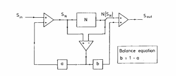
The attached is the canonical combination of error feedback and error feedforward.
Depending on whether a = 0 and b = 1 or b = 0 and a = 1, you get one or the other.
Anything in between, you get something, errr.. in between. N is the distorting part.
As long as you keep b = 1 - a for obvious reasons. This is by Malcolm Hawksford.
Jan
Depending on whether a = 0 and b = 1 or b = 0 and a = 1, you get one or the other.
Anything in between, you get something, errr.. in between. N is the distorting part.
As long as you keep b = 1 - a for obvious reasons. This is by Malcolm Hawksford.
Jan
Attachments
''but I would have expected for a feedforward to be implemented as a pre distortion to be applied somewhere between the class A amp output, and the dumpers.'' - well there you go!I do wonder if some of the terminology used is a bit confusing in its application to this circuit, I know what a bridge in the traditional sense is. And I observe that at least 2 places in the circuit where components can be "tuned" to make a distortion null, in alexcp's simulation, and my own simulation tweaking the bridges C and L for the glitch minimum. I am not quite so sure what feed forward is, but I would have expected for a feedforward to be implemented as a pre distortion to be applied somewhere between the class A amp output, and the dumpers. This would primarily correct for the crossover glitch resulting in less of a continuity disturbance. I don't see that in the circuit, just a resistor providing a little bit of drive across the dead zone.
Have enjoyed @alexcp simulation, I managed to get almost -400dB. Getting my brain to understand things is a bit like stirring cold treacle at the moment, but intrigued by the strong gain dependent null, and interested to look at the frequency sweep, will it all fall to pieces? the suspense.
I, rightly or wrongly, do not view it as ''Pre-distortion''. I view it as a short transients which appear where there are no fundamentals, which are shaped and fed back to the input of the Class A amplifier, where they are amplified; in the hypothetical case, by 30db and quickly force the CDs into conduction, away from the non linear zone. The faster that happens, the less the need for negative feedback. This does not exclude the use of conventional feedback, but the plots given earlier comparing Sugden to Quad, doesn't seem to suggest, there is much by way of conventional feed back? - certainly up to 1 watt output. Beyond however, it could be somewhat different.
In modern terms, all this could be achieved by a ''shadow digital circuit'', which could accurately determine when the dumpers should switch on and ensure that they did so. beyond their non linear region. All in all, this seems to be a means of ''Out of Band Control'', where products are being used to control the performance of the fundamentals. I don't know if any of this makes sense, but it appears to me that it is not a question of inhibiting distortion, but using the products, albeit at a very early onset, to arrest the production of products.
@jan.didden, jut to help my understanding, those, "opamps" are unity gain differential input.
Thanks
Thanks
Walker was very, very clever. The CD amp is like Class AB in that is works as Class A on small signal, and the non-linearity of the output stage kicks in only when the signal is above a threshold. The difference is, of course, that in CD there is no quiescent current of Class AB. Unfortunately it doesn't come without price: (1) the Class A amplifier in CD has to deal with ugly(-er) distortion products, which happily intermodulate any useful signal at the input stage, and (2) the frequency response of the current dumper is not so good without current, which limits the use of feedback to help the input stage be more linear.In a CD, at crossover, you will see a nice continuous flat gain line. No bias setting, yet basically no crossover nonlinearity.
I'll post a few more sims on "balancing the bridge" later today.
So, about that "bridge".
My sims in #41 above used ideal amplifiers with frequency-independent gain. It is a useful abstraction, but a realistic amplifier's gain falls with frequency. In a feedback amplifier (and any current dumping amplifier uses feedback!), this makes necessary some form of frequency compensation. Walker (as other designers of the era) used single slope, dominant pole compensation by a "Miller" capacitor:

With the capacitor, the loop gain is no longer a constant 100 (=40dB). It turns south at about 1kHz with the values shown (that's the pole), falls at 20dB/decade as frequency rises (that's single slope) and hits unity (zero dB) at about 100kHz:

As there is less feedback at higher frequencies, the distortion level at the output of the current dumper goes up starting at 1kHz:

The "pre-distortion" at the output of the Class A stage (=the input of the current dumper) is the sum (in dB) of the two graphs above and stays relatively constant as frequency changes, decreasing only when the amplifier runs out of loop gain:

To null the distortion at the load, one needs to add proportionally less, by 20dB/decade, of current dumper output or more of Class A output at higher frequencies. Walker made a frequency-dependent adder with an inductor and a resistor:

Nulling with an ideal (zero DCR) inductor of the value L=RRC (3.3μ≈2×9k×180p) works a little better than feedback alone, but nowhere near the theoretical zero - compare -40dB of compensation here with -322dB in post #41:

The reason, of course, is that my frequency-dependent summer doesn't work too well at frequencies below the pole, where the loop gain is constant.
One way to improve nulling is to add an appropriate DC resistance (1/100 of R3, to account for the constant loop gain of 100 below the pole) to the inductor:


Walker solved this in a different way: by adding loop gain. With more loop gain, the pole is pushed to a lower frequency, and nulling is improved:


However, adding a few milliohms of DC resistance to the inductor ruins nulling again 🙁
No matter what you do, nulling is finicky. It is sensitive to component values, which have tolerances and change with temperature, humidity, age, and other factors. Feedback, on the other hand, is a much more robust solution.
My sims in #41 above used ideal amplifiers with frequency-independent gain. It is a useful abstraction, but a realistic amplifier's gain falls with frequency. In a feedback amplifier (and any current dumping amplifier uses feedback!), this makes necessary some form of frequency compensation. Walker (as other designers of the era) used single slope, dominant pole compensation by a "Miller" capacitor:
With the capacitor, the loop gain is no longer a constant 100 (=40dB). It turns south at about 1kHz with the values shown (that's the pole), falls at 20dB/decade as frequency rises (that's single slope) and hits unity (zero dB) at about 100kHz:
As there is less feedback at higher frequencies, the distortion level at the output of the current dumper goes up starting at 1kHz:
The "pre-distortion" at the output of the Class A stage (=the input of the current dumper) is the sum (in dB) of the two graphs above and stays relatively constant as frequency changes, decreasing only when the amplifier runs out of loop gain:
To null the distortion at the load, one needs to add proportionally less, by 20dB/decade, of current dumper output or more of Class A output at higher frequencies. Walker made a frequency-dependent adder with an inductor and a resistor:
Nulling with an ideal (zero DCR) inductor of the value L=RRC (3.3μ≈2×9k×180p) works a little better than feedback alone, but nowhere near the theoretical zero - compare -40dB of compensation here with -322dB in post #41:
The reason, of course, is that my frequency-dependent summer doesn't work too well at frequencies below the pole, where the loop gain is constant.
One way to improve nulling is to add an appropriate DC resistance (1/100 of R3, to account for the constant loop gain of 100 below the pole) to the inductor:
Walker solved this in a different way: by adding loop gain. With more loop gain, the pole is pushed to a lower frequency, and nulling is improved:
However, adding a few milliohms of DC resistance to the inductor ruins nulling again 🙁
No matter what you do, nulling is finicky. It is sensitive to component values, which have tolerances and change with temperature, humidity, age, and other factors. Feedback, on the other hand, is a much more robust solution.
Thanks Jan,Another way to view it is as follows.
There is a main feedback loop from output to input.
But when the dumpers start to conduct, additional feedback from Z4 (the impedance in series with the dumper output) is generated.
This is significant: in any 'normal' feedback amp, the feedback factor is constant (it's normally a two resistor divider).
But in a CD amp, the feedback factor changes depending on what the dumpers do!
In a normal feedback amp, the loop gain determines how much the distortion is reduced, and this is, to a first approximation, a constant as long as the gain is constant.
In a CD amp, the gain is not constant, and depends on what the dumpers are doing.
The feedback factor change with dumper operation means that the distortion reduction is constant, whether the dumpers are on or off.
If you look at the gain during crossover in a 'normal' feedback amp, you see a discontinuity because the gain changes during crossover.
In a CD, at crossover, you will see a nice continuous flat gain line. No bias setting, yet basically no crossover nonlinearity.
This also means that as long as the class A amp can provide the required output, the speed of the dumpers is unimportant.
Whenever they come on or off, at whatever speed, the additional feedback factor will follow the current through Z4.
Jan
But is the feedback ''Selective''? Surely, it must be related to only the transition region of the dumpers, as that is the only region the Class A needs to apply control? Beyond this point, the Dumper voltage mirrors that of the Class A amp and assuming there is no phase error, their action is complimentary, the dumper current is increasing/decreasing over linear part of their transfer characteristic; ditto the class A, so no requirement for feedback - indeed, error signal will be zero??????
Hi @alexcp I have enjoyed your simulations very much. In my attempt to develop my understanding, I implemented on my machine. I have an observation, the first voltage controlled voltage source(?) with a gain of 1000. My understanding of the circuit, the "high Quality" class A amp, is a current source, who' output impedance is high, but will approach 1.5k at some high frequency. It seems the nice null in the simulation occurs because the simulated VAS has a voltage output?If we combine the output of the VAS and the output of the OPS in the 1:100 proportion, we get a distortion-free output. (Here, -322dB is as close to negative infinity in dB as LTSpice can get):
- Home
- Amplifiers
- Solid State
- QUAD current dumping class A output power?