Generally in these formulae, the coil diameter/radius is to the middle of the wire, or group of wires if layered, not to the bobbin diameter and not the outer diameter.
That would make sense.
Doing a search on the Internet for Wheeler's Formula would tend to agree.
Re-iterating the figures means I've got to rewind the coils.
16T = 1.528uH
20T = 1.989uH
Doing a search on the Internet for Wheeler's Formula would tend to agree.
Re-iterating the figures means I've got to rewind the coils.
16T = 1.528uH
20T = 1.989uH
Last edited:
modeling results much closer to your first guess of 1.333:1 ratio, rather than my squared modeling giving a 1.69:1 ratio.
Have you tried making a tank circuit of the inductor with a known capacitor say 100nf, I use my fluke 179 to measure the cap for accuracy, I hope my dmm is accurate.
Then put a small resistor in series with tank circuit and connect it to a sig gen,
if you measure over the tank circuit with a scope, while changing the frequency of the sig gen, you'll find the point where the signal rises to its greatest value then starts to decrease again, at the highest value, the resonant frequency,
The you can use the formula for the tank circuit at resonance to determine the L of the inductor.
I'm also busy winding an inductor and have the same questions.
I'm hoping the method I posted above is accurate enough.
Regards
Is there any rule of thumb relating L to C in a tank circuit ?
My oscillator only just manages 100KHz, I have some good quality 33uF caps that would push the resonant frequency down to about 60KHz.
My oscillator only just manages 100KHz, I have some good quality 33uF caps that would push the resonant frequency down to about 60KHz.
Can I assume from the silence from the normal team that you can make a tank circuit from the most extreme components.
I use a series pair of resistor and inductor.
Apply a sinewave to the pair.
Measure the voltage acros the resistor
Measure the voltage across the inductor
Compare the two results.
Adjust the frequency until you get an exact match between resistor voltage and inductor voltage.
You now have the F-3dB frequency of that filter pair and you know the resistance.
Practical measurement of tiny inductances ~ 1uH at audio frequencies is not as simple as it might be for larger, typical loudsdspeaker coils. Typical hand-held multimeters also give up below 100uH as their accuracy falls apart. DMMs typically can't even handle AC above ~4 kHz accurately anyway. Unless you have a 'scope and an accurate AC millivoltmeter or two, there will be problems.
This short video shows the bridge principle at work in an interesting method using basic gear with worksheet calcs. It is still about larger values and dodgy equipment, but given the claimed precision of 0.1 uH, might be helpful for understanding the issues.
Coil Inductance, Measurement and Calculation.wmv - YouTube
DMMs set to AC voltage used to COMPARE equal voltages work very well at higher frequencies.
I have used cheap DMMs to compare at frequencies upto and even beyond 50kHz and got excellent accuracy
BTW,
the link in post 188 is the same method as I suggested in post 187.
I have used cheap DMMs to compare at frequencies upto and even beyond 50kHz and got excellent accuracy
BTW,
the link in post 188 is the same method as I suggested in post 187.
Last edited:
Yes, that results in the same determination of equivalent impedance in a tank circuit but the nulling method shown is more elegant for a demonstration, which is what the post was about. However, my old TRMS meter shows instability and eventually displays "E" ~ 10 kHz. That is one reason for the caveats, particularly when you don't know the standards of DMMs that members have. If I use that old meter paired with a current model that is rated accurate to 100kHz or use it alone by comparing uncertain readings, you can understand the problems.DMMs set to AC voltage used to COMPARE equal voltages work very well at higher frequencies.....I have used cheap DMMs to compare at frequencies upto and even beyond 50kHz and got excellent accuracy.....the link in post 188 is the same method as I suggested in post 187.
I think simple diode/average AC detection is the more dependable technique with typical multimeters. I also doubt many DIYs will have have pairs of the same model meter anyway but it would have been amusing to swap meters on our demonstrator. 😉
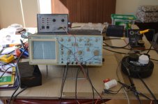
I'm hoping that my trusty oscilloscope and audio frequency generator will provide the necessary dip.
I do need to use quite a large cap - circa 10uF in order to stay within the limits of my generator.
I do need to use quite a large cap - circa 10uF in order to stay within the limits of my generator.
just use the same DMM and swap one probe to the beginning or end of the two component string.
The other probe is clipped to the junction between the two components.
When the DMM meter reads the same voltage then you know that "by comparison" the two voltages are the same. One does NOT NEED to know the voltage, simply that the voltages are the same.
The other probe is clipped to the junction between the two components.
When the DMM meter reads the same voltage then you know that "by comparison" the two voltages are the same. One does NOT NEED to know the voltage, simply that the voltages are the same.
Katie or Dad.
You don't need a capacitor.
A resistor of low tolerance is far better than a wide tolerance capacitor.
You don't need a capacitor.
A resistor of low tolerance is far better than a wide tolerance capacitor.
Anyone after the obsolete J503, I can vouch for these guys. Just tested a batch of four of them and they are all genuine.
E-Bay "tubeshunter"
E-Bay "tubeshunter"
Last edited:
What sort of frequency are you looking at though ? My trusty audio generator just about manages 100KHz.
Take a guess at the inductance.
Use 90kHz as your maximum usable frequency.
Calculate the resistor required to give your F-3dB filter frequency.
repeat for 10kHz and again for 1kHz.
If all three resistors are values you have, then do three measurements to see if the inductance is the same at all three frequencies.
Use 90kHz as your maximum usable frequency.
Calculate the resistor required to give your F-3dB filter frequency.
repeat for 10kHz and again for 1kHz.
If all three resistors are values you have, then do three measurements to see if the inductance is the same at all three frequencies.
Even at 50kHz I'm getting silly values for the series resistor to equal Xl.
2 x pi x f x L
1.5uH at 50kHz is 0.47 Ohms
2.0uH at 50kHz is 0.63 Ohms
I don't think this method is going to be practical with such low value chokes.
2 x pi x f x L
1.5uH at 50kHz is 0.47 Ohms
2.0uH at 50kHz is 0.63 Ohms
I don't think this method is going to be practical with such low value chokes.
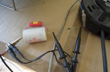
Using the tank circuit method with a measured 33uF polypropylene audio grade Mundorf cap, I get a maximum at 16.666666 kHz.
In my maths that makes my 2.0uH coils actually 2.76uH. Possibly a touch too big for the Quad clone.
I had to use a 100R series resistor to get meaningful results.
In my maths that makes my 2.0uH coils actually 2.76uH. Possibly a touch too big for the Quad clone.
I had to use a 100R series resistor to get meaningful results.
Attachments
Last edited:
Using exactly the same method my 1.5uH coils produced a max at 19.23kHz.
So my 1.5uH coils are actually 2.07uH
I guess I can use these as 2.0uH. Shame there are only two of them.
So my 1.5uH coils are actually 2.07uH
I guess I can use these as 2.0uH. Shame there are only two of them.
I'm going to have another go at making the coils this week with slightly smaller diameter cores, so they will fit the boards. But at least I now have a method for measuring them.
- Home
- Amplifiers
- Solid State
- QUAD 909 Clone