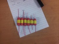
Hi a 1.5uH air cored inductor is pretty small - there are numerous sites that show how you can wind your own - in the pic below is one I made alongside one 606 board however I ended up using 2 of these -B82111BC16 - EPCOS - INDUCTOR, 3UH, 20%, 9A, 220MHZ | Farnell UK
..which are 9A devices so in reality unlikely to saturate
inductor
..which are 9A devices so in reality unlikely to saturate
inductor
I agree the 1.5uH and 2uH are pretty small but the 20uH becomes seriously huge when air cored, some 412 turns at 10mm.
But why bother going air cored, it's only there for stability and current through it is minimal
the inductance of an air cored is proportional to turns².
If 9T is ~1uH, then 18T gives ~4uH and 36T gives ~16uH.
Fewer than 40T would give ~20uH.
One could get the resistance below 10milli-ohms.
If one were looking for 3uH then <4milli-ohms would the an achievable target.
Yes, less than the 6milli-ohms of the ferrite cored, linked in post141
If 9T is ~1uH, then 18T gives ~4uH and 36T gives ~16uH.
Fewer than 40T would give ~20uH.
One could get the resistance below 10milli-ohms.
If one were looking for 3uH then <4milli-ohms would the an achievable target.
Yes, less than the 6milli-ohms of the ferrite cored, linked in post141
I posted a spreadsheet years ago that had an air cored inductor included in among a few other calculators and the Dr Cherry version of the Thiele output network.
found it:
http://www.diyaudio.com/forums/solid-state/120748-zobel-no-zobel.html#post1475396
2mm diam wire on 15.6mm diam bobbin.
12.4 Turns in 3 layers give 3uH and 4.8milli-ohms.
http://www.diyaudio.com/forums/solid-state/120748-zobel-no-zobel.html#post1475396
2mm diam wire on 15.6mm diam bobbin.
12.4 Turns in 3 layers give 3uH and 4.8milli-ohms.
Last edited:
If winding the inductors onto a resistor as a former, what value resistor would you use ?
A 2.5W would give you the body size but they are generally quite low resistance. I suppose you could strip the resistor film off the body.
A 2.5W would give you the body size but they are generally quite low resistance. I suppose you could strip the resistor film off the body.
Quad quote these at +/- 10% (ISTR). Are they not actually that critical.
Could 20uH be replaced with the current standard of 22uH.
Could 20uH be replaced with the current standard of 22uH.
Hi - afaikt that is not a critical component so 22uH would be fine. You could try these that are radial leaded 20uH Your Search Results | Farnell UK | Results

Here's a nice easy calculator that you can plug any convenient values of what you have to hand for air-cored inductors: Pronine Electronics Design - Multilayer Air Core Inductor Calculator
For example, 20 uH with 18 AWG comes to 50 milliohms with a 10mm ID x 20mm L coil, in 3 layers of 19 T. If you want to have the leads emerge at the same end, you can recalculate for an even number of layers.
To make coils, I prefer a plastic bobbin such as a plain tube ball or felt pen. I drill the bobbin size twice through a scrap of aluminium sheet and roughly snip into 2 cheekplates to restrain the coil whilst winding. If you made a dog's breakfast of drilling the holes in thin metal, all the better, as this will wedge the plates in position nicely on plastic or metal bobbins. If too loose, a little persuasion with a ball pein hammer to the cheek face, will reduce the hole size. Drill a 1.2 mm hole in one cheekplate, alongside the bobbin, and this is your start lead exit. Wind away, nice and close. You may need to fit 2.3m or so on there with the example.
Test for value if you have the gear but hold the final turns in place with a wide cable tie or similar and soak the thing with Polyurethane lacquer or even clear nail polish and let it dry out and set firm in a warm, ventilated place, to keep it in shape when you later peel off the plates. The bobbin tube can remain, trimmed to length. Perhaps then cable-tie it to the PCB. At least that's what I would prefer, for security of a fairly heavy item, almost 20mm D x 20mm H .
Last edited:
As I was using fairly sturdy 1mm wire it was easy to secure the winding with a heatshrink cover.
Nice pics of the smaller coils too. 18 AWG also happens to be 1mm but the suggestions were really for the more difficult, multi-layer L1 of 20uH.
It occurs to me that with the series resistor in the circuit of L1, the LC forms the compensating correction for the output stage's bridge network. I would have thought that accuracy was fairly important but if someone can better inform, I'll stand corrected. The original may be ferrite cored but it's very small, going by the Quad 606 SM illustration but I doubt it needs 1mm wire, even air-cored.
It occurs to me that with the series resistor in the circuit of L1, the LC forms the compensating correction for the output stage's bridge network. I would have thought that accuracy was fairly important but if someone can better inform, I'll stand corrected. The original may be ferrite cored but it's very small, going by the Quad 606 SM illustration but I doubt it needs 1mm wire, even air-cored.
I notice that the 606/707/909s were often produced with 2N3773 or MJ15003.
The OP was going to use 2SC5200.
In a new-retro build which would be the better choice ?
The OP was going to use 2SC5200.
In a new-retro build which would be the better choice ?
There's not a lot in common there.
2N3773 is a heavy current slug of device and 2SC5200 is a 30 Mhz flyweight. I think it's about cost, as the far better choice in a TO264 plastic pack would be MJL21193/4/5/6. You would still need enough devices to match the sheer cranking power and short-circuit proof quality of the original 3 x T03s - assuming that's what you expect without a protection relay, limiters or you happen to have some ESLs to drive etc.
2N3773 is a heavy current slug of device and 2SC5200 is a 30 Mhz flyweight. I think it's about cost, as the far better choice in a TO264 plastic pack would be MJL21193/4/5/6. You would still need enough devices to match the sheer cranking power and short-circuit proof quality of the original 3 x T03s - assuming that's what you expect without a protection relay, limiters or you happen to have some ESLs to drive etc.
I'm tempted to go with the MJ15003 as those were used by Quad in the 909.
With the sheer number of fakes around the 2SC5200 are not available from my main supplier.
With the sheer number of fakes around the 2SC5200 are not available from my main supplier.
Last edited:
- Home
- Amplifiers
- Solid State
- QUAD 909 Clone