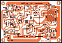
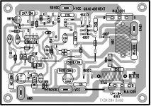
Here are a few notes about picking components and building my 405
- OpAmps. My original preference was for an OPA134. But due to the current chip shortage, none can be found. I am almost certain the ones offered on eBay/Aliexpress are fake. If building using PTH, use an IC socket and temporarily put in a TL071. More OPA134's are expected next year.
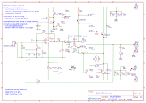
- Transistors. Q1A/B is not critical. Vce of at least 50v for Q2 and 80v for Q3. Q3 possibly needs to handle more current. I have not measured, but I chose an Ic of at least 1A and Vce of 100v for Q3. Any medium power TO220 will suffice for Q7/8. As big a transistor you can find for Q9/10, but be careful about Ft. Ft on the original transistors were sub 10Mhz. So anything over that, RF precautions apply, e.g, keeping leads and PCB traces short and power decoupling tight.
- Bridge. Balanced bridge (C8, R38, 20, 21 & L2) = low THD. Formula is R38 * R20||21 = L1/C8. It's easy to get 1% tolerances for resistors and capacitors, but inductors commonly have a 20% tolerance. I started with a 3uH inductor and unwound it till I got about 2.8uH. Low inductances are difficult to measure. Great if you have an LCR bridge, but I did not. I put a known 1% capacitor in parallel with L2 to form a tank circuit and measured its oscillation on a DSO to determine its inductance down to 1% accuracy.
- Passive component ratings. R30/31 form part of the class A amp and get very hot. Minimum 3W and keep it away from the board. 1W for R7, 8, 10, 22, 33, 37, 38, Rx and Rled. I used 1/2w for the rest, plus some 1/4w for front end signal. 10v Tantalum for C2. 1/2w for zeners D1/2. 1A is sufficient for L4.
- Others. I did not use Qp. Just short the PWR jumper.

Hi, is this version available as bare pcb?In fact, not all LJM letters are my products.
Because many people imitate my products.
In addition, quad405 is very simple. If it is made by me, there will be no problem under normal circumstances. In fact, I made 405-2 It uses only one inductor.
There is no obvious difference in performance. But more people like the older version.
Maybe because it looks better with MJ15024. The 405-2 uses c5200
Hello Altus
greetings please can you look at my pcb component
layout getting DC at the output
warm regards
You need to provide more details. DC output of 20mv is normal. How much DC are you getting? +/-?
I would check polarity of all components, transistor BCE's are in the right holes, diode polarity. Some transistors of the same type may have different pinouts with different suffixes, esp for TO92's. Then check all jumpers are in.
After that, start probing voltage from the source to output with 0v as the reference
- Voltage supply of op amp +/- 15v
- Input and inverting input of opamp should be 0v
- Output of opamp should be close a few mV
- Apart from Q1, All the transistors should be close to rail voltage for pins connected to the rail side and close to 0v for pins connected to the output side when no signal is present.
Last edited:
Hello Altus
greetings many many thanks for helping me to build
Quad 405 Sound quality has exceeded my
expectations very pleased with the result can
2SC2713 be substituted with 2SD669.
warm regards
Andrew
greetings many many thanks for helping me to build
Quad 405 Sound quality has exceeded my
expectations very pleased with the result can
2SC2713 be substituted with 2SD669.
warm regards
Andrew
where is the next generation? what was the level of Oldfag's scheme, it remains so today.
Quasi-complementary output assembly in class C - why?
Quasi-complementary output assembly in class C - why?
Congratulations, very fast build.Hello Altus
greetings many many thanks for helping me to build
Quad 405 Sound quality has exceeded my
expectations very pleased with the result can
2SC2713 be substituted with 2SD669.
warm regards
Andrew
What caused the initial DC problem that you had?
The 405 is a very pleasant amp. I suspect it has a high damping factor as well, so produces a nice accurate bass, especially for larger and multi driver speakers that are difficult to drive.
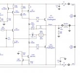
Yes, the +ve side of the MJE15033 and R30/31 form part of the class A side of the amp, so current is always flowing and they are always hot.Hello Altus
greetings sound is very sweet full of details only
positive side mje15033 driver transistor gets hot
is that normal enclosed my final pcb layout
warm regards
Andrew
The negative side MJE15033 is the class C driver, so should stay cool with no load.
Also your C10 is too close to R30/31. Both resistors run at 60c or more above ambient temperatures. If you put in into a case, they will easily exceed 100c. C10, being an electrolytic, will have a short life.
If you do not want to change the layout of the board, just solder c10 on the opposite side of the PCB
Glad you liked this Andrew. I was listening to some Vinyl using this amp yesterday, excellent.Hello Altus
greetings many many thanks for helping me to build
Quad 405 Sound quality has exceeded my
expectations very pleased with the result can
2SC2713 be substituted with 2SD669.
warm regards
Andrew
this statement is not true, if you look at the transient characteristics in the load, then the output impedance of the 405th firstly depends on the frequency, and secondly, it is different for the positive and negative half-waves. at a supply voltage of +/- 50 volts, I do not recommend connecting speakers with an impedance of less than 8 ohms. it is also desirable to use exactly thespeakers with maximum linear impedance to minimize the capacitive nature of the load, which greatly affects the feedback.The 405 is a very pleasant amp. I suspect it has a high damping factor as well, so produces a nice accurate bass, especially for larger and multi driver speakers that are difficult to drive.
To increase the damping of acoustic systems in the load, QUAD engineers paralleled the transistors of the output stage in the later versions of the 606/707/909.
I think the scheme for any needs further refinement despite the subjective positive reviews.greetings please can you look at my pcb component
layout getting DC at the output
C8 seems to be in the bridge, but in fact it turns out to be connected between two low-resistance points of the circuit, on the one hand it is the collector Q7 limited by resistor R38, on the other hand, the input impedance is low from the R36 emitter.
due to the addition of D6, the direct current through the inductance L2 and the driver transistor Q8 was increased, which is why the R34L4 circuit was introduced to limit the current through it, although it would be more logical to install a Baksandall diode, and it is even more logical not to increase the current through this transistor and install medium power transistor, which significantly reduces the base area and significantly increases the speed of this transistor - its work is important precisely on the transient characteristics.
Q2 has lost its power current limit, which requires an additional heatsink for cooling, and its non-linearity has also increased due to the increased influence of miller input capacitance.
P.S. I would be ashamed in front of Peter Walker for such "new generations" ....
We need to be clear what the design briefs are for the "Next Generation" 405 and stay focused on them.P.S. I would be ashamed in front of Peter Walker for such "new generations" ....
The Quad 405 has a distinct tonal characteristic. Not perfect, but pleasant. But it also has a high noise floor, inputs that are too sensitive for today's devices, relatively high distortion and uses obsolete, poor performing components by today's standards.
I always do an ABX test for all my amplifiers. Modern amplifiers are getting more difficult to distinguish in ABX tests, which suggest they reproduce the source with good accuracy. I did an ABX test on the 405 vs. a MA12070p digital amp. The MA12070 is known to be tonally accurate from an earlier ABX test. I could identify the 405 very quickly. The 405 lacked sparkle in the higher ranges and perhaps that impedes it's ability to image well (longer listening needed to confirm this).
However, standalone, the 405 has a pleasant sound. Some refer to it as warm/laid back, perhaps due to its limited slew rate. Perhaps its the class A section that produces a lot of 2nd order distortion (needs to be measured). But whatever it is, this is the '405' sound and we can't call it a '405' if it doesn't sound like that. And a lot of people seem to like this sound, like tube amps, imperfect, but nice.
So the design brief is clear. Make something with a '405 sound' while addressing it's shortcomings as highlighted above. The challenge is balancing the number of design changes vs. the risk of altering its original tonal characteristics.
There are some excellent 405 inspired designs such as tvicol's Q17 amp, which seem to address the slew rate limitation, possibly resulting in better transients and opens up the upper ranges. I'm sure it will sound good, but will it still sound like the original Quad 405?
If I could blindfold Peter Walker and put him in an ABX test, I'm certain he would be able to recognise the '405 Next Gen' amp and possibly be quite pleased with the sound.
Ok, please focus on improving the quality of the base 405...We need to be clear what the design briefs are for the "Next Generation" 405 and stay focused on them.
The Quad 405 has a distinct tonal characteristic. Not perfect, but pleasant. But it also has a high noise floor, inputs that are too sensitive for today's devices, relatively high distortion and uses obsolete, poor performing components by today's standards.
of course, 50 years have already passed, during this time a lot could be modified, and the QUAD engineers themselves clearly suggest ways to improve for cloning by radio amateurs
You write so much about measurements, but you don't mention at all important characteristics for quality improvement, such as the gain of the open loop at 1kHz and 20kHz, also the gain level at the bases of the output stage, and the actual depth of negative feedback in close loop mode...So the design brief is clear. Make something with a '405 sound' while addressing it's shortcomings as highlighted above. The challenge is balancing the number of design changes vs. the risk of altering its original tonal characteristics.
your assumptions are absolutely wrong and do not correspond to the understanding of the quality of sound reproduction. The whole topology of the 405 is based on increasing the reaction speed in the feedback loop, any slowdowns lead to sound degradation. It's not entirely appropriate to do worse than Walker did 50 years ago...
That would be frustrating for the late Peter Walker, as he was convinced no-one could hear any difference between two well-designed amplifiers. He even organized a challenge where people compared QUAD amplifiers and could win a substantial amount of money if they heard a difference.If I could blindfold Peter Walker and put him in an ABX test, I'm certain he would be able to recognise the '405 Next Gen' amp and possibly be quite pleased with the sound.
Anyway, if there are audible differences, it doesn't necessarily have to be due to something non-linear, it could as well be the minor bass and treble roll-off due to the built-in second-order high-pass at 14 Hz and first-order low-pass at 40 kHz. There is also the polarity inversion, if you don't swap the loudspeaker wires.
Last edited:
A good hint at the features of the circuit, though Polak suggested shaping them a little later in a different way in order to change the phase less, but there is not even close to such a nuance in the "new gen".it could as well be the minor bass and treble roll-off due to the built-in second-order high-pass at 14 Hz and first-order low-pass at 40 kHz.
- Home
- Amplifiers
- Solid State
- QUAD 405 Next Gen