Interesting. With R12 = 3.3 kohm and C6 = 1 nF, it should be about 48 kHz (I thought it was 40 kHz, apparently I misremembered). Maybe something else is slightly peaking.
I did consider the frequency roll offs. I have R12 = 2.7k / C6 = 1nF which should give a low pass of 48khz and C1 = 0.68uF / R3 = 22k for a high pass of 10Hz.Anyway, if there are audible differences, it doesn't necessarily have to be due to something non-linear
But realistically, my speakers roll of at 50Hz and my ears can barely discern anything above 10khz and definitely nothing over 15khz. So I suspect the frequency response limits may not explain the 405's signature in the ABX tests I've done.
I'm still curious, so planning to do a frequency and distortion sweep once I have the time
It would be 40 kHz if you included the 560R, but Quad amp of every model I've ever measured has been ~55 kHz, out of many hundred. Seems to be a theme.Interesting. With R12 = 3.3 kohm and C6 = 1 nF, it should be about 48 kHz (I thought it was 40 kHz, apparently I misremembered). Maybe something else is slightly peaking.
Only if you ignore the DC servo, R4, R5, and C2. There's another LF pole there.and C1 = 0.68uF / R3 = 22k for a high pass of 10Hz.

ExactlyOnly if you ignore the DC servo, R4, R5, and C2. There's another LF pole there.
such a simple servo has a very high quality factor, because the effect of the reactive load is much greater than the active value of the load, with the peak at 2.4 kHz, although the time constant seems to be very large. What this means in practice is the increased non-linearity under the NFB and the dependence of the sound on the parameters of the capacitor in the servo, and in the most sensitive range of human hearing.
In later versions of Quad amplifiers, the engineers abandoned such a servo by using an active circuit with an even longer time constant. Although it is possible to reduce the quality factor of this servo (405th) by damping the storage capacitor in the integrator circuit - this will slightly reduce the depth of the NFB, but increase the linearity of the gain over the entire frequency band.
Last edited:
maybe it doesn’t make sense for anyone, but it works great for me in the practical implementation of such damping...
P.S. I don’t have the habit of theorizing, I only write what was developed, done and tested in practice ...
P.S. I don’t have the habit of theorizing, I only write what was developed, done and tested in practice ...
Mind you, my calculations are for the inverting circuit, like the original QUAD 405 and 405-2. I had overlooked that the circuit in post #1 has been modified into a non-inverting circuit.2. Using an op-amp with FET input, you can easily redesign the DC loop such that you don't need an electrolytic capacitor in the DC feedback anymore, see https://www.diyaudio.com/community/threads/redesigning-quad-405-dc-bias-loops.339643/ Mooly's simulation results in that thread are with an incorrect resistor value.
Mind you, my calculations are for the inverting circuit, like the original QUAD 405 and 405-2. I had overlooked that the circuit in post #1 has been modified into a non-inverting circuit.
Not had the chance to look into the details on how it works, but will definitely check it out the next time someone brings me a QUAS 405 or a clone to fix. Thanks
I can give suggestions for modifying quad405. Is to reduce the gain. This can significantly reduce thd.
In addition, reduce the capacitance of LPF. It can reduce the high-frequency attenuation. The details are better.
In addition, do not replace the operational amplifier.
I have a quad 44 original, between 405-2, L12-2 and mx50x2 wich one you think will be best for me sound wiseI would apreciate if you can give me those sugestions and instructions as i want to assemple your 405-2 boards.
check out this thread:
https://www.diyaudio.com/community/threads/quad-current-dumping-class-a-output-power.406673/
https://www.diyaudio.com/community/threads/quad-current-dumping-class-a-output-power.406673/
Here is my Quad 405 Evolution Journey.
I built the clone in 2020 and I was impressed with the sound quality.
Luckily, my friend Patrick had the skills to investigate the cloned 405, see the mistakes and make a modern version of this circuit using readily available components. This new circuit took advantage of modern SMC components and modern transistors.
I transplanted the clone circuits for the new circuits (plug-and-play).
The end result is nothing short of stunning. The warmth of the original with the improved clarity and resolution.
I'm also now the proud owner of the original Quad 405 Mark I from the late 70's, still sounds brilliant.
Just in case anyone is interested, I measured the distortion performance of the amp.
Done using a Focusrite Scarlet Solo Gen 3 as the ADC and source. REW as the measuring software.
Very happy with the distortion. Not low, but even order harmonics dominates the show. Done at 1W and 5W, similar performance.
Patrick


Patrick
Done using a Focusrite Scarlet Solo Gen 3 as the ADC and source. REW as the measuring software.
Very happy with the distortion. Not low, but even order harmonics dominates the show. Done at 1W and 5W, similar performance.
Patrick
Patrick
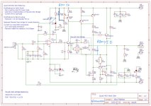
Final Schematic & Gerbers
After chat72's questions on a few missing components on the original schematic, I realized that I had not posted the final version of the circuit diagram.
I did remember uploading the final diagram on DIYAudio, but it turned out to be replies to PM's and not to this thread. My bad.
Here's the final circuit and the gerber for the PCB as well.
Attachments
Is this your “as built” schematic ? There are two extra resistors on PCB, r9 and r10 and no qp. I read value of r9 and r10 from the picture.
Thanks for pointing that out. Have uploaded the final schematic. The original one was meant as a draft to solicit opinions on the circuit.
I have not used QP in the final circuit. The passive zener regulator provided more than enough stable current to drive the TLE2071 op-amp. You notice a jumper pad on the PCB which I soldered to bypass QP.
- Home
- Amplifiers
- Solid State
- QUAD 405 Next Gen