I was fortunate to have listened to two Chinese Quad 405 clones recently and was pleased with the sound. My only issue was they both sounded slightly different, being assembled from a different set of components. Apart from the TO-3 MJ15025G transistors being most likely fake, the rest of the 405's transistors became obsolete a long time ago, and it's really up to the vendors on what substitutes they make.
I was keen to build a pair, but rather than to rely on the random quality of parts in a Chinese clone, and then putting in well known modifications by Keith Snook and Bernd Ludwig, I thought I might as well design one with all the latest mods and control the quality from the start.
A few things I had in mind:

The first thing I noticed is all my favorite low noise TO-92 transistors are now obsolete. The only through hole ones left are general purpose types, not so good for the amp front end. But the good news is that quite a few have reincarnated in SMD form. Eg, the 2SC1845 is now FJV1845, BC560 is now BC860.
So SMD it is. Working with SMD also opens the window to a far better selection of passive parts. 1%, 50ppm thin film resistors by the likes of Vishay or Susumu available in any value and most importantly, in stock.
I do have some concerns on the newer TO-3P transistors are much faster with Ft of 20Mhz or more. The MJ15025's are manageable, but I'm trying to avoid the troublesome mounting of TO-3 transistors. I'm hoping that a good PCB design and proper power supply decoupling will help ensure stability.
I'm wondering if anyone out there been successful with newer TO-3p transistors such as the 2SC5200 or the MJW3218's that I'm planning to use?
Also appreciate any comments on the circuit if anything is obviously wrong, or if you have a preference of doing it differently, before I start designing the PCB
Patrick
I was keen to build a pair, but rather than to rely on the random quality of parts in a Chinese clone, and then putting in well known modifications by Keith Snook and Bernd Ludwig, I thought I might as well design one with all the latest mods and control the quality from the start.
A few things I had in mind:
- All components must be current and readily available from reputable sources like Mouser, Digikey, etc. Obsolete parts are a pain, NOS are expensive and the affordable ones most likely fake
- Double sided PCB design with proper ground planes and short traces to minimize noise and ultrasonic issues (we are working with much faster transistors than 40 years ago)
- Popular mods baked into the design
- Individually balanced Maxwell-Wein bridge for lower distortion (With a 20% typical tolerance for inductors 😵, its likely to be out of balance without some trimming)
The first thing I noticed is all my favorite low noise TO-92 transistors are now obsolete. The only through hole ones left are general purpose types, not so good for the amp front end. But the good news is that quite a few have reincarnated in SMD form. Eg, the 2SC1845 is now FJV1845, BC560 is now BC860.
So SMD it is. Working with SMD also opens the window to a far better selection of passive parts. 1%, 50ppm thin film resistors by the likes of Vishay or Susumu available in any value and most importantly, in stock.
I do have some concerns on the newer TO-3P transistors are much faster with Ft of 20Mhz or more. The MJ15025's are manageable, but I'm trying to avoid the troublesome mounting of TO-3 transistors. I'm hoping that a good PCB design and proper power supply decoupling will help ensure stability.
I'm wondering if anyone out there been successful with newer TO-3p transistors such as the 2SC5200 or the MJW3218's that I'm planning to use?
Also appreciate any comments on the circuit if anything is obviously wrong, or if you have a preference of doing it differently, before I start designing the PCB
Patrick
Last edited:
Great work!!! The BC860 is designated with "A" and "B", do you use a matched pair in one SMD package? If yes what is the part number?
will be following this thread with interest 🍿😉
correct me if I'm wrong but didn't Ludwig Bernd wrote something on 5200's?
anyway, just a suggestion, your choise are SMD's... would it be trouble to create extra pad as option for classic TO transistor mounting?
have you consider doubling output devices option?
correct me if I'm wrong but didn't Ludwig Bernd wrote something on 5200's?
anyway, just a suggestion, your choise are SMD's... would it be trouble to create extra pad as option for classic TO transistor mounting?
have you consider doubling output devices option?
I'm using the BC860 "C" the one with the highest gain, just a few cent's extra, so why not.Great work!!! The BC860 is designated with "A" and "B", do you use a matched pair in one SMD package? If yes what is the part number?
Yes, I do remember a matched pair in one SMD package, but I can't remember the part number. Anyway, I'm using the BC850 pair just as a constant current regulator, so matching is not critical.
Most early transistor amplifiers, like the 1969 John Linsey Hood, and this Quad 405 don't tend to use long tail transistor pairs for inputs and feedback. This is where a matched pair would shine.
My guess is that manufacturing process then was not so tight with a great variation in gains. And because of that, using a long tail pair would probably not have yielded the performance boost needed to justify the use of an extra very expensive transistor.
Yes, Bernd did mention the 2SC5200 as a possible modern replacement, but he also went on to mention that higher Ft was not a trivial thing to ignore. And he left it at that.will be following this thread with interest 🍿😉
correct me if I'm wrong but didn't Ludwig Bernd wrote something on 5200's?
anyway, just a suggestion, your choise are SMD's... would it be trouble to create extra pad as option for classic TO transistor mounting?
have you consider doubling output devices option?
I've seen a few Chinese clones using the 2S5200's but on much earlier 405 revisions with an inductor each for the output transistors. I suppose the inductor will slow the output transistors down and keep them stable.
I'm planning to move on from the latest 405 revision where the output transistor inductors have been replaced by a single smaller inductor for only the driver.
I'm favoring the beefier NJW3281 over the 2SC5200 as its rated at 200W vs. 150W. Both have the same Ft of 30mhz suggesting similar risks of oscillation. So if I need to deal with oscillations, might as well have the more powerful transistor installed.
I did consider the TIP35 with a much lower Ft of 3mhz, but it's is only rated for 125W. Looking at it's SOA chart, I run the risk of exceeding it with a lowish impedance speaker.
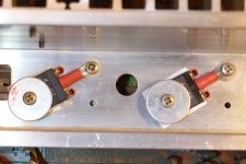
At the moment, I'm planning to mount the TO-3P's flush on 90x45mm aluminum plates as compared to 90 degree angle mount for a metal TO-3. The 90x45 matches the dimensions of the Quad 405 mount. I'll then have my PCB match the 90x45mm size and sit on top of the aluminum mount with some stand offs. Very compact, but easily do able with SMD, but unfortunately, not enough to mount parallel output transistors.
If my setup works, more than happy to design a board for classic TO3 mounting, and even a double transistor one if anyone needs one
Yes, I do remember a matched pair in one SMD package, but I can't remember the part number. Anyway, I'm using the BC850 pair just as a constant current regulator, so matching is not critical.
OK, thanks a lot! The matched pair for the BC850 seems to be the BCM847...
At the moment, I'm planning to mount the TO-3P's flush on 90x45mm aluminum plates as compared to 90 degree angle mount for a metal TO-3. The 90x45 matches the dimensions of the Quad 405 mount. I'll then have my PCB match the 90x45mm size and sit on top of the aluminum mount with some stand offs. Very compact, but easily do able with SMD, but unfortunately, not enough to mount parallel output transistors.
If my setup works, more than happy to design a board for classic TO3 mounting, and even a double transistor one if anyone needs one
It's possible to use TO3 and TO264 in one footprint (I read EasyEDA can import KiCAD files):
Attachments
Last edited:

Interesting! I've just put together a PCB as a direct replacement for my 405 boards (so TO-3's in the original locations) and am currently building up the first one. Schematic wise, I've included the mods that I've done on my original boards, and looks like this:

Compared to yours, I've left in the output crowbar, and left the opamp stage as inverting. The later boards added R44 75 Ohm in parallel with L2, which I see you don't have. Also I didn't see the benefit of the opamp +ve supply emitter follower (especially with the curernt source mods described below).
I've used a similar current source for TR2 biasing, but with a couple of detail differences:
1. Split R13 into two (R13 and R0) and kept C5 to give increased HF supply rejection
2. Kept R14 across TR0 c-e, set to 1k Ohm
I found with the modified current source, there was an enhanced turn-off thump, with the speaker output having a large negative transient.
Comparing the modified current source with the original, it can be seen that the modified current source without R14 (blue trace) maintains its current down to much lower supply voltages than the original (yellow trace). This was causing TR7 to be turned off whilst still at a fair supply voltage, allowing the base of TR8 to be pulled to the -ve rail by R30/31 and hence driving the output to the -ve rail also.
Adding R14 causes the current to fall to zero at ~10v (green trace) whilst maintaining the enhances output impedance around 50v, and gave no noticeable turn-off thump. So you might like to make provision for R14 in order to replicate these results.

Looking forward to seeing how your board progresses!
Compared to yours, I've left in the output crowbar, and left the opamp stage as inverting. The later boards added R44 75 Ohm in parallel with L2, which I see you don't have. Also I didn't see the benefit of the opamp +ve supply emitter follower (especially with the curernt source mods described below).
I've used a similar current source for TR2 biasing, but with a couple of detail differences:
1. Split R13 into two (R13 and R0) and kept C5 to give increased HF supply rejection
2. Kept R14 across TR0 c-e, set to 1k Ohm
I found with the modified current source, there was an enhanced turn-off thump, with the speaker output having a large negative transient.
Comparing the modified current source with the original, it can be seen that the modified current source without R14 (blue trace) maintains its current down to much lower supply voltages than the original (yellow trace). This was causing TR7 to be turned off whilst still at a fair supply voltage, allowing the base of TR8 to be pulled to the -ve rail by R30/31 and hence driving the output to the -ve rail also.
Adding R14 causes the current to fall to zero at ~10v (green trace) whilst maintaining the enhances output impedance around 50v, and gave no noticeable turn-off thump. So you might like to make provision for R14 in order to replicate these results.
Looking forward to seeing how your board progresses!
...or even just fit the TO264 to a TO3 footprint like that
Sorry, these are TO3Ps (not TO264s), a TO264 would need extra holes to fit (as shown in my footprint)...
Yes, you are right, putting both the opamp supply emitter follower and the TR2 biasing mods in together does not solve the turn off thump problem.Also I didn't see the benefit of the opamp +ve supply emitter follower (especially with the curernt source mods described below).
I'll probably need to decide on one or the other but leaning towards a TR2 bias mod, and your arrangement looks interesting. I see that you have done the before and after testing/sims of the circuit, but have you had the chance to actually implement it yet?
I've left in the output crowbar, and left the opamp stage as inverting
The reason for not adding the crowbar circuit in mine is the difficulty in getting the avalanche trigger device. The original one used by the 405 is now obsolete. The closest alternative is a diac, but the lowest breakover voltage is above 30v. I think the breakover of the device in the 405 is only 5v. I'm really not familiar with these devices.
I noticed that you have a triac in place of the trigger device. No idea how that works, or is it just there in place of the original since it's a symbol that I've never seen before nor can identify and probably not in EasyEDA's library?
That's a very elegant way to retrofit a plastic TO-3P into a metal TO-3 position. I also like the large washer to spread out the pressure on the device....or even just fit the TO264 to a TO3 footprint like that:
Thanks for the PCB footprint for the common T0-3 metal/plastic pads. It's easier to implement if you already have space for the metal TO-3 cans, but I'm starting from a position of a 90x45mm compact board. Probably easier to do another separate board design for accommodate metal tO-3's.
Here's the unfinished PCB of my board and the planned location of the transistors.
I'll probably need to decide on one or the other but leaning towards a TR2 bias mod, and your arrangement looks interesting. I see that you have done the before and after testing/sims of the circuit, but have you had the chance to actually implement it yet?
Yep, that is how all my original 405 boards are currently configured. I initially did the current source mod without R14 and noticed the power-off thump, so did some probing with a 'scope and the analysis presented above to devise the solution adding R14, they are now nice and quiet on turn-off.
You could of course include a footprint for R14 and do your own experiments to decide whether to use it or not. Similarly for the extra emitter follower, you could make provision to easily short the b-e and have flexibility with that too.
The reason for not adding the crowbar circuit in mine is the difficulty in getting the avalanche trigger device. The original one used by the 405 is now obsolete. The closest alternative is a diac, but the lowest breakover voltage is above 30v. I think the breakover of the device in the 405 is only 5v. I'm really not familiar with these devices.
I noticed that you have a triac in place of the trigger device. No idea how that works, or is it just there in place of the original since it's a symbol that I've never seen before nor can identify and probably not in EasyEDA's library?
For the new board I'm curerntly building up I've just re-used the BS08D trigger device from the original board (along with the heatsink bracket, R30/31 and L2). It is a 3-terminal device with the centre terminal unconnected, hence my use of a triac symbol to get a suitable 3-hole footprint for the PCB. Keith Snook lists the 2N4992 as equivalent on his website. Both are still available from Farnell US (but with a large additional delivery charge to me in the UK). Have also seen the BS08D listed by Dada Electronics in the EU.
I'm chatting in class D next door. Then I happened to see quad405 DIY.
I think I made it very early. Maybe I can send a picture for others to refer to.
I have more experience with quad405. I have been making it since 2005.
I know the principle of almost every component very well; If you have any questions, you can ask me.
I think I made it very early. Maybe I can send a picture for others to refer to.
I have more experience with quad405. I have been making it since 2005.
I know the principle of almost every component very well; If you have any questions, you can ask me.
Attachments
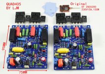
LJM, Thanks for your offer to help. I think both the two Quad 405 clones that I listened to were your design. Both had LJM mark on the board. One sounded very nice, but the other not so good. Both of them also had the TO-3 MJ15035 transistors on board.I'm chatting in class D next door. Then I happened to see quad405 DIY.
I think I made it very early. Maybe I can send a picture for others to refer to.
I have more experience with quad405. I have been making it since 2005.
I know the principle of almost every component very well; If you have any questions, you can ask me.
I am very curious and wondering why every Quad 405 clone from China offered on eBay or Aliexpress follows the older design, i.e. with 3 large inductors? Is it because it is more stable and more tolerant to newer faster transistors with a high Ft?
Patrick
In fact, not all LJM letters are my products.LJM, Thanks for your offer to help. I think both the two Quad 405 clones that I listened to were your design. Both had LJM mark on the board. One sounded very nice, but the other not so good. Both of them also had the TO-3 MJ15035 transistors on board.
I am very curious and wondering why every Quad 405 clone from China offered on eBay or Aliexpress follows the older design, i.e. with 3 large inductors? Is it because it is more stable and more tolerant to newer faster transistors with a high Ft?
Patrick
Because many people imitate my products.
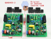
In addition, quad405 is very simple. If it is made by me, there will be no problem under normal circumstances. In fact, I made 405-2 It uses only one inductor.
There is no obvious difference in performance. But more people like the older version.
Maybe because it looks better with MJ15024. The 405-2 uses c5200
Attachments
MJW3281 VERY GOOD.I was fortunate to have listened to two Chinese Quad 405 clones recently and was pleased with the sound. My only issue was they both sounded slightly different, being assembled from a different set of components. Apart from the TO-3 MJ15025G transistors being most likely fake, the rest of the 405's transistors became obsolete a long time ago, and it's really up to the vendors on what substitutes they make.
I was keen to build a pair, but rather than to rely on the random quality of parts in a Chinese clone, and then putting in well known modifications by Keith Snook and Bernd Ludwig, I thought I might as well design one with all the latest mods and control the quality from the start.
A few things I had in mind:
So here's the first pass of the design:
- All components must be current and readily available from reputable sources like Mouser, Digikey, etc. Obsolete parts are a pain, NOS are expensive and the affordable ones most likely fake
- Double sided PCB design with proper ground planes and short traces to minimize noise and ultrasonic issues (we are working with much faster transistors than 40 years ago)
- Popular mods baked into the design
- Individually balanced Maxwell-Wein bridge for lower distortion (With a 20% typical tolerance for inductors 😵, its likely to be out of balance without some trimming)
View attachment 1071166
The first thing I noticed is all my favorite low noise TO-92 transistors are now obsolete. The only through hole ones left are general purpose types, not so good for the amp front end. But the good news is that quite a few have reincarnated in SMD form. Eg, the 2SC1845 is now FJV1845, BC560 is now BC860.
So SMD it is. Working with SMD also opens the window to a far better selection of passive parts. 1%, 50ppm thin film resistors by the likes of Vishay or Susumu available in any value and most importantly, in stock.
I do have some concerns on the newer TO-3P transistors are much faster with Ft of 20Mhz or more. The MJ15025's are manageable, but I'm trying to avoid the troublesome mounting of TO-3 transistors. I'm hoping that a good PCB design and proper power supply decoupling will help ensure stability.
I'm wondering if anyone out there been successful with newer TO-3p transistors such as the 2SC5200 or the MJW3218's that I'm planning to use?
Also appreciate any comments on the circuit if anything is obviously wrong, or if you have a preference of doing it differently, before I start designing the PCB
Patrick
However, it should be noted that it actually improves the performance compared with njw0281 or 2sc5200.
In fact, the quad405 output power tube does not heat up. It is in class B state. So it has no special requirements. TIP35 or d1047 can also be satisfied.
contrary. Tip42 pushes the transistor. Have higher requirements. Because it's very hot. Pay attention to safety.
You have a very good judgment. MOSFET is not used. MOSFET may be attractive. But this is wrong.
Sorry, I couldn't help myself from reading these two sentences...In fact, not all LJM letters are my products.
Because many people imitate my products.
It isn't a tube, it is a transistor, and it is in Class C state, and it does heat up when driven. Otherwise why all the heatsinking?In fact, the quad405 output power tube does not heat up. It is in class B state
Good to see that you have made a 405-2 kit with based on the later Quad design. I probably did not notice it because I was looking at those with the MJ15024.In fact, not all LJM letters are my products.
Because many people imitate my products.
In addition, quad405 is very simple. If it is made by me, there will be no problem under normal circumstances. In fact, I made 405-2 It uses only one inductor.
There is no obvious difference in performance. But more people like the older version.
Maybe because it looks better with MJ15024. The 405-2 uses c5200
Did you have any stability issues with the c5200 with a much higher Ft of 30Mhz? That's my main concern about using the MJW3281
I saw it with my own eyes and heard with my own ears. Two similar boards with the LJM brand. One looked better made than the other and the better made one had a nicer sound.Sorry, I couldn't help myself from reading these two sentences...
I suspect the other was a copy of the original LJM
- Home
- Amplifiers
- Solid State
- QUAD 405 Next Gen