https://www.dadaelectronics.eu/uplo...als/Quad-306-Upgrade-Revision-Manual-V1.4.pdf
Also wondered if I should fit the Dada recommended 62k resistor in R6 (120k).
Also wondered if I should fit the Dada recommended 62k resistor in R6 (120k).
Erm 🙂 I suspect the diodes might be more wishful thinking as much as anything else. I haven't really looked into different mods tbh.
The additional 10k in the simulation seems to do very little (surprisingly). It marginally worsens the distortion but only by a miniscule amount.
The additional 10k in the simulation seems to do very little (surprisingly). It marginally worsens the distortion but only by a miniscule amount.
Cleaned the board and the 19v DC offset came back 🙁
I replaced the 330pf copper foil polystyrene (R6) and DC offset is back to 00.1mV, but I'm a bit worried that, that was a coincidence. Is there a test I can do on the cap to see if it's faulty? It measures 330pf with my DE-5000 LCR meter.
I replaced the 330pf copper foil polystyrene (R6) and DC offset is back to 00.1mV, but I'm a bit worried that, that was a coincidence. Is there a test I can do on the cap to see if it's faulty? It measures 330pf with my DE-5000 LCR meter.
Measuring for leakage in the cap is about all you can do using a high ohms range but what you are seeing sounds a little bit more like you have some hidden physical issue around that area. perhaps a bad joint or another part touching something it shouldn't.
Pressing a prodding the board is a good test as you watch the offset.
Pressing a prodding the board is a good test as you watch the offset.
Copper foil polystyrene is soldered back in.
The only place that seems to make the offset jump up, is when I touch L1 with cotton bud (cotton tip cut off), Or any sharp jolts seem to do it.
I've poked and prodded both sides of the board, but can't find anything.
Offset is back to where it should be, but there's obviously something wrong somewhere 🙁
That sounds very strange. I suppose swapping the coils between channels might prove if the coil was intermittent but that would be a really weird fault. The thing to be aware of doing that is the possibility of removing the coil (if it is faulty) might actually temporarily fix it. So the fault may not swap channels but the bad channel would then be good if that makes sense.
Swapped L1 over and the problem moved over to the other side.
Where can I buy a pair of 20uH 0.68R inductors? Or whatever value will work.
Where can I buy a pair of 20uH 0.68R inductors? Or whatever value will work.
https://www.hificollective.co.uk/catalog/000-0813-0-02mh-jantzen-air-core-wire-coil.html ? DCR 0.10R though...
EDIT: I can't see DCR matters much because R13 is 9.1R
Or these https://www.ebay.co.uk/itm/292537769035?epid=26018537604&hash=item441c9c1c4b:g:BdEAAOSwUDla4JMv
EDIT: I can't see DCR matters much because R13 is 9.1R
Or these https://www.ebay.co.uk/itm/292537769035?epid=26018537604&hash=item441c9c1c4b:g:BdEAAOSwUDla4JMv
Last edited:
Wow, I'm amazed tbh. That must be such a rare sort of fault.Swapped L1 over and the problem moved over to the other side.
Where can I buy a pair of 20uH 0.68R inductors? Or whatever value will work.
I'll have a think... its unknown territory really. What I would say is that you should replace both to keep things equal. I'm guessing the original part is only a small one. Can you tell if its on a ferrite core or if it is air spaced?
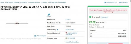
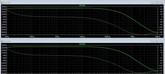
22uH from CPC. Let me have a play with the sim and see what sort of effect that coil has on things.
https://cpc.farnell.com/epcos/b82144a2223k/inductor-axial-22uh/dp/TF00568

https://cpc.farnell.com/epcos/b82144a2223k/inductor-axial-22uh/dp/TF00568

I just cut the heat shrink that holds the inductor together, and it fell apart. It was only twisted together at the top. The solder holding it together must have failed.

It's now soldered together with some more heat shrink over the top, with no DC offset flickering on either channel when I tap the inductors 🙂
We got there in the end.
Thanks for helping Mooly. Now I can plug it in a listen to some music 🙂
It's now soldered together with some more heat shrink over the top, with no DC offset flickering on either channel when I tap the inductors 🙂
We got there in the end.
Thanks for helping Mooly. Now I can plug it in a listen to some music 🙂
Wonderful 🙂 It's been a good one has this 😉
Something like the inductor could so easily have temporarily 'worked' once swapped over. Amazing.
Something like the inductor could so easily have temporarily 'worked' once swapped over. Amazing.
Looks like I spoke too soon 🙁 It's distorting quite badly. I'll have another look tomorrow if I get a chance...
At least we fixed one problem.
At least we fixed one problem.
The voltages seem to have changed quite a bit.
C10 40.7v
C11 38.1v
T1
B 42.8mV
C -6.74v
E 0.665v
T2
B 6.79v
C 38.9v
E 6.17v
T3
B 0.695v
C 38.9v
E 23.5mV
T4
B 40.8v
C 00.2mV
E 40.7V
T5
B 38.9v
C 1.18v
E 39.5v
T6
B 39.5v
C 1.18v
E 40.1v
T7
B 40.1v
C 1.18v
E 40.6v
T8
B -0.742v
C -38.1v
E 0.37mV
T9
B -0.103v
C 40.7v
E -00.4mV
T10
B -38.1v
C -03.4mV
E -38v
T11
B -0.527v
C 40.8v
E 0v
T12
B -0.530v
C -30.1v
E 0v
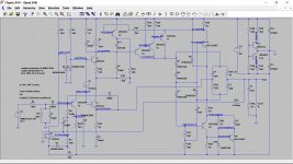
All those look good, DC conditions all correct. This shows the working voltages in the sim for comparison.

First prove by swapping over that the speakers and input are OK. It has to be done...
Beyond that... hmmm... and this is getting into scope territory to see what is going on. No parts lifted for testing that you have not noticed and are not soldered back in place?

First prove by swapping over that the speakers and input are OK. It has to be done...
Beyond that... hmmm... and this is getting into scope territory to see what is going on. No parts lifted for testing that you have not noticed and are not soldered back in place?
Swapped over the DAC RCAs, and it stayed in the same side, swapped over the speaker cables, and it moved to the right speaker. So it's a problem with the left channel of the amp. I've looked over the board, but can't see anything wrong.
When I turn the amp off with the music still playing, it gets more and more distorted in the left channel until it goes quiet. I noticed that someone on here had a similar problem, but theirs had the opposite symptoms - it sounded less distorted when he turned his amp off (His problem was T7).
I haven't used a scope before, but have seen them, and they look pretty complicated. Have you got any recommendations for a cheap scope? Second-hand off ebay.co.uk maybe? Perhaps there are some Youtube tutorials that I could watch...
- Home
- Amplifiers
- Solid State
- Quad 306 High DC offset in left channel
