Interesting, except that all the PL380 blurb clearly shows ISOTOP packaged devices (also quote -- "a single pair of large-die FETs"), not the APT power module.
And this is an *enormously* heavy-duty module (110A 1250W) which I can't believe QSC would use, it would be way over-rated. Mind you APT do even bigger ones like the APTM50UM13SAG (250A 3300W)...
If you were going to go the module route, you can get a complete half-bridge (with series-parallel diodes) in a single module like the APTM50AM38STG which will be cheaper and switch faster than two separate modules.
Mind you, I bet "cheaper" is only relative, I suspect these modules cost several hundred dollars each...
Ian
Eva said:I thought that class D was not about producing lots of heat...
Indeed, which is why body diodes with Trr>100ns are *bad* news for power MOSFETs in class D amps (switching current more than doubled by reverse recovery = switching power loss more than quadrupled)...
So if you want really high efficiency (say >95%) you not only need to switch fast but also either need to use 100V MOSFETS (which have Trr<50ns) or series/parallel hyperfast diodes to keep the current out of the MOSFET body diodes -- IGBTs just aren't fast enough, even the IR Warp2 series.
Or maybe some semi-resonant switching scheme to make sure the FET current is always forward at turnoff, but this also increases power dissipation in the FET which is about to turn off as well as needing some way to recover the energy stored in the inductor.
I've been looking at all this because I've been investigating using Zetex's DDFA chipset for high-power multichannel PA amps (2kw/4ohms), the problem is it switches at 850kHz so switching loss is a *big* issue...
Ian
Ian
Interleaving “slow” power sections is another possibility for high power//low emi, if you solve the current distribution problem...
iand said:
IGBTs just aren't fast enough, even the IR Warp2 series.
Ian
http://ixdev.ixys.com/DataSheet/99044.pdf
fredos said:Hmmmm....Seem to tast good!
I already made a recipe out of it and it tastes yummy!
😀 😀 😉
50ns of exponentially-falling current tail from Ic to 0 are always better than 150ns of linearly rising cross-conduction from 0 to 2*Id 😉
Eva said:50ns of exponentially-falling current tail from Ic to 0 are always better than 150ns of linearly rising cross-conduction from 0 to 2*Id 😉
Tail current of IGBT is beneficial sometimes!🙂
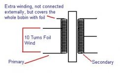
Eva said:Winding interleaving is intended to reduce leakage inductance. How a single extra turn can cover the entire winding? Is it a piece of copper foil?
Evita, see the attached diagram. The winding is done by copper foil.
Attachments
Eva said:Does it cover the core too?
Only Bobbin is covered with this extra turn
Winding order is S😛+ET:S
The extra turn has no external connection, its end is terminated and insulated with tape, but it covers the whole bobbin just like a shield.
The core has another copper foil wrapped around it covering the bobbin and core externally, but its connected to Live negative BUS of SMPS.
Hi, Kanwar,
Do you know mosfet type that has smaller size (TO264, TO247) about 30A, 200-300V, that already has internal series+parrarel dioda like APT50um25s you pointed above?
Do you know mosfet type that has smaller size (TO264, TO247) about 30A, 200-300V, that already has internal series+parrarel dioda like APT50um25s you pointed above?
lumanauw said:Hi, Kanwar,
Do you know mosfet type that has smaller size (TO264, TO247) about 30A, 200-300V, that already has internal series+parrarel dioda like APT50um25s you pointed above?
http://ixdev.ixys.com/DataSheet/16fd3bdd-f163-4cf6-b758-0fc143100898.pdf
Thanks 😀
That IGBT IXGK60N60 looks good too. Will the future classD use that highspeed IGBT or Mosfet (with series+parrarel diodes)?
That IGBT IXGK60N60 looks good too. Will the future classD use that highspeed IGBT or Mosfet (with series+parrarel diodes)?
#Workhorse i had a similar idea some time ago, maybe its same:
to cancel the switching spikes, transfered by the stray-cap. from the coil, you could use a switching signal with inverted phase, and couple this with some stray-cap. also...
so most transfered energy from stray-cap. is canceled, without needing a big Y - cap.
maybe this "free" extra turn does exactly this...
alfsch said:#Workhorse i had a similar idea some time ago, maybe its same:
to cancel the switching spikes, transfered by the stray-cap. from the coil, you could use a switching signal with inverted phase, and couple this with some stray-cap. also...
so most transfered energy from stray-cap. is canceled, without needing a big Y - cap.
maybe this "free" extra turn does exactly this...
Exactly, The extra turn is out of phase with primary winding, thereby helps in minimizing distributed stray capacitance. 🙂
lumanauw said:Thanks 😀
That IGBT IXGK60N60 looks good too. Will the future classD use that highspeed IGBT or Mosfet (with series+parrarel diodes)?
I am already in to the IGBT recipe......😀
Workhorse said:
Switching 50A at 400V (20kW!) loss at 125C per IGBT is 2.1mJ, total switching loss 4.2mJ per transition which is just over 1kW when switched at 250kHz, or 5% loss (if I've added up the numbers correctly).
Not bad, but still no good for 850kHz switching (17% loss)...
Ian
iand said:
Switching 50A at 400V (20kW!) loss at 125C per IGBT is 2.1mJ, total switching loss 4.2mJ per transition which is just over 1kW when switched at 250kHz, or 5% loss (if I've added up the numbers correctly).
Not bad, but still no good for 850kHz switching (17% loss)...
Ian
No one except you is saying for switching at 850kHz...........🙂
250kHz is optimum!
- Status
- Not open for further replies.
- Home
- Amplifiers
- Class D
- QSC PL380 amp