Hello,
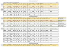
New 1.3.8 table with sound review for the FQA46N15 / IXTQ36P15P. I also added 2 new columns with THD and SNR.
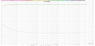
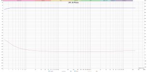
Concerning the v1.3 board, the curves are the same as with v3 except for the SNR and THD which is better with the v3 board. The overshoot is stronger on the v1.3 board than with the v3 board. To remove the overshoot on the V1.3 board, I have to lower the gate resistor R15 even more. We also see some defects in SIN 20KHz with the v1.3 board (small breakage).
The spectrum harmonic curve for the FQA46N15 / FQA36P15 pair is different between v1.3 and v3 (but not the sweep). I should try with the same transistors on each board. There may be a problem with the FQA36P15 that I tried with the v3 board. The sweep curves are the same.
Finally, I have the same overshoot problem with V1.3 as with v3. Forced to reduce the gate resistor R15. The mystery of the Q17 remains.
As a reminder, the difference between a v1.3 and a v3 boards is the replacement of Q7 KSC1845 by the cascode LSK170B / DN2540 and a new way of wiring the CSS of BS250P. An evolution of the circuit that iTiberius had proposed before disappearing.
It's hard to choose between the 4 pairs I listened to. Finally, the FQA46N15 / IXTH48P20P pair seems the most balanced.
Now it's up to you to listen and make your own choice.
Regards,
Stef.
New 1.3.8 table with sound review for the FQA46N15 / IXTQ36P15P. I also added 2 new columns with THD and SNR.
Concerning the v1.3 board, the curves are the same as with v3 except for the SNR and THD which is better with the v3 board. The overshoot is stronger on the v1.3 board than with the v3 board. To remove the overshoot on the V1.3 board, I have to lower the gate resistor R15 even more. We also see some defects in SIN 20KHz with the v1.3 board (small breakage).
The spectrum harmonic curve for the FQA46N15 / FQA36P15 pair is different between v1.3 and v3 (but not the sweep). I should try with the same transistors on each board. There may be a problem with the FQA36P15 that I tried with the v3 board. The sweep curves are the same.
Finally, I have the same overshoot problem with V1.3 as with v3. Forced to reduce the gate resistor R15. The mystery of the Q17 remains.
As a reminder, the difference between a v1.3 and a v3 boards is the replacement of Q7 KSC1845 by the cascode LSK170B / DN2540 and a new way of wiring the CSS of BS250P. An evolution of the circuit that iTiberius had proposed before disappearing.
It's hard to choose between the 4 pairs I listened to. Finally, the FQA46N15 / IXTH48P20P pair seems the most balanced.
Now it's up to you to listen and make your own choice.
Regards,
Stef.
Attachments
Last edited:
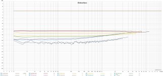
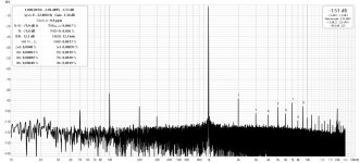
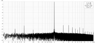
I think your results are very strange. The higher order harmonics almost have the same level as the 3rd. except in the first measurement with the FQA36P15.
That one looks normal. All the other looks very strange and no correlation to what I see in my measurements, no matter the level.
That one looks normal. All the other looks very strange and no correlation to what I see in my measurements, no matter the level.
With a -20dB attenuator and 10Vrms output, I have the same curves and the same THD.
As for the curve and gate resistor stories, I don't understand either. I'm reaching my level of incompetence here.
If you're not too far away, I can send you some PCBs from v3. I have some left.
Stef.
As for the curve and gate resistor stories, I don't understand either. I'm reaching my level of incompetence here.
If you're not too far away, I can send you some PCBs from v3. I have some left.
Stef.

Very kind of you and it could be interesting, but I do not have the components to populate the board. I live in Denmark.With a -20dB attenuator and 10Vrms output, I have the same curves and the same THD.
As for the curve and gate resistor stories, I don't understand either. I'm reaching my level of incompetence here.
If you're not too far away, I can send you some PCBs from v3. I have some left.
Stef.
Karsten
Hi Steff
Do you have any of the original boards, so you could make a comparison with those.?
Otherwise I could send my two boards to you , so you could compare them to the new versions.
You live in France right?
Do you have any of the original boards, so you could make a comparison with those.?
Otherwise I could send my two boards to you , so you could compare them to the new versions.
You live in France right?
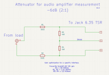
It is not the attenuator that saturates, but the level into the analyzer is too high. Such an attenuator cannot saturate.The 14W curve is not good. Saturation of the -6dB attenuator I currently use.
Would you be interested in me sending you the two original boards with FQA one one and ITX on the other?
You would need to mount them on a heatsink, as it would be too expensive to send mounted on a heatsink.
Eventually PM me.
You would need to mount them on a heatsink, as it would be too expensive to send mounted on a heatsink.
Eventually PM me.
Is the gainconfiguration of the input OpAmp the same on the Koldby board and the board of Stef?
Is Koldby using the input filter and Stef probably not?
Is Koldby using the input filter and Stef probably not?
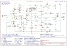
I use 1.2V sensibility (R16=47K, R17=4k75, R6=196R) and all TH component. I can try with original values (R17=3k3; R6=100R) but I already tried with R17=5k1 and R6=100R. I also tried with C17=1uF to be sure. No change.
I also have to try with an OPA1641 (need to solder one). I currently use OPA1611.
The big difference between the PCBs is the coil. On PCB for the original, air coil for my versions.
No input filter for the v3 board. No input filter on the Tiberius' too.
I can activate the input filter on the v1.3 board to try but I don't believe it.
Stef.
The bridge, R25 ?
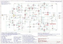
I just finished a voltage survey on v3 with FQA46N15 / IXTQ36P15P. I'll clean them up and post them later. At first glance, everything looks good.
Stef.
I just finished a voltage survey on v3 with FQA46N15 / IXTQ36P15P. I'll clean them up and post them later. At first glance, everything looks good.
Stef.

Stef , is it possible to post which way is the best to go regarding which transistors and FETs ?
Hello,
After various tests, I finally found a setting that improves things with the new MOSFETs. I have only tested the FQA46N15 / IXTQ36P15P pair for the moment.
If I increase the current of the ClassA stage, the overshoot disappears completely and the spectrum improves. THD and SNR also improve.
So I changed R10 and R13 to 8R2 instead of 9R1. The total consumption of the board goes from 180mA to 206mA.
A track to work on.
Stef.
Attachments
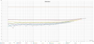
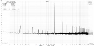
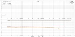
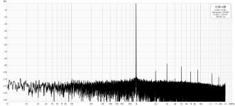
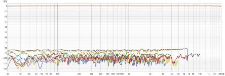
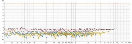
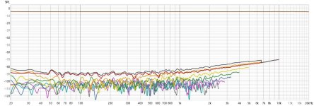
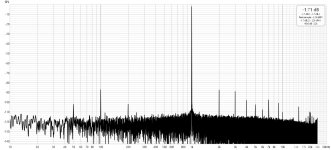
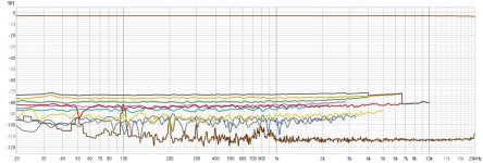
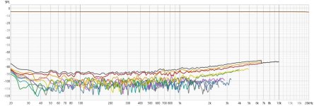
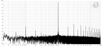
Now I can verify the what Stef has been saying all the time. concerning the difference between ITX an FQA p-mosfets.
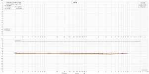
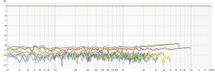
I took the time to change my measuring system, so I now also use REW.
My Behringer UCA222 is not as good as the soundcard Stef uses as can be seen in the loopback measurements, but the results shows the same difference in distortion spectrum just the same. Mine are the original PCB with 2 pairs of MOSFets .
In the original , the Class A bias is evnen less as the resistors R10 and R13 are 10 Ohms and the total consumption for the hole amp is only 100 mA, so I would think the problem is even worse for the original Q17 as the class A stage has to drive two pairs.
As can be seen , the class A has no problems with FQA types.
I haven´t yet tried to increase the Class A bias, but I will eventually.
Attachments
-
 Loop back RTA.jpg185 KB · Views: 54
 -
 LOOPBACK DIST.jpg140.3 KB · Views: 52
 -
 FQA DIST 1W.jpg136.7 KB · Views: 47
 -
 FQA DIST 90 W.jpg138.9 KB · Views: 47
 -
 FQA RTA 1W.jpg201.5 KB · Views: 48
 -
 FQA RTA 90W.jpg184.3 KB · Views: 52
 -
 ITX DIST 1 W.jpg142 KB · Views: 47
 -
 ITX DIST 90 W.jpg137.4 KB · Views: 45
 -
 ITX RTA 1W.jpg178.6 KB · Views: 45
 -
 ITX 91W.jpg147.2 KB · Views: 58

- Home
- Amplifiers
- Solid State
- Q17 - an audiophile approach to perfect sound