Hello,
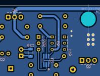
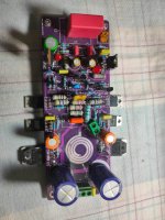
I did a placement test on NDC7003P to replace the two BS250P on the Turbo. That doesn't look bad. I selected a TSOT-23-6 HandSoldering footprint for the brave who would like to weld it.
If someone can verify that I did not plant myself in the wiring. 😉
Stef.
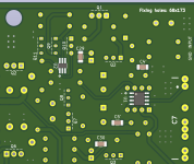
I did a placement test on NDC7003P to replace the two BS250P on the Turbo. That doesn't look bad. I selected a TSOT-23-6 HandSoldering footprint for the brave who would like to weld it.
If someone can verify that I did not plant myself in the wiring. 😉
Stef.
Attachments
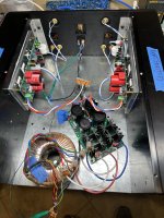
Q17 Turbo SBC version! +50 WHP.I made a little homemade jig to wind the coils using a T-handle valve cover hold down from a Chevy V8 small block🤣


Good option to have Stef, nice job. I would have tried the NDC7003P, but I’m very close to powering up both channels. I’m using a reclaimed amplifier chassis, the heatsinks are overkill! How hot do your heatsinks get?
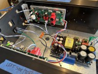
Using a lab supply, I cautiously powered up each Q17 amp board individually to verify no shorts or magic smoke would be released. Success!!
The lab supply has a maximum +/-32V so I switched to a +/-52V MicroAudio SMPS in order to take voltage measurements.
Channel#1:
R3 0.645V (4.3mA)
R13 0.615V (62mA)
Q8 17.58V (gate)
R11/12 2.87V (across resistor)
Q13/14(output) +/-47.5V
Opamp psu +/-14.10
Data for channel#2 differs less than 2%, didn’t bother posting the numbers.
Attachments
Vunce, I would be interested in a sound comparison of Q17 vs PeeCeeBee V4H. Which will be the winner. 😀
Thx.
Thx.
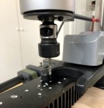
Wow, that's quite the piece of hardware. I couldn't justify the spend, but there's a certain fascination (for me at least) in machine tools and it's so sweet when a tool makes a formerly difficult/time consuming job routine....
Superb hardware. I finally received the missing part. I am doing some testing. 5 seconds to make a tap. Very easy to use. You lower the handle of the drill, it blocks when you get to the bottom of the hole, you raise the handle of the drill and the tap comes out. If you pull too hard, it slips.
A real pleasure to tap now. Too bad this device is so expensive.
Stef.
Attachments
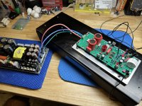
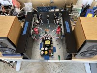
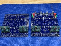
Another Q17 is born!
Built in a massive repurposed testbed chassis initially using a +/-52V SMPS. This amp runs so cool, does it even need a heatsink? (just joking, of course)
I was hearing some higher frequency background noise/hiss from the speakers when the music was paused and suspected the smps could be the source. Swapped out the smps for a linear psu. No more noise/hiss, silence at the tweeter, just a slight ground loop hum that will be addressed.
The latest build is always the greatest but Q17 sounds very good on the bench, really good detail and bass weight. Because of these good first impressions the 'real' build will utilize a dual mono linear supply with active rectification and DC speaker protection. Maybe even try the IXYS P-chan mosfets 😉.
Thank you Tibi for sharing this well supported project, Q17 is a keeper!
Also want to thank Stef1777 for sharing his Q17-Turbo pcb layout, it has been a pleasure to work with. Your interactive BOM and part placement location was a first for me and very helpful.
Attachments
Hi Vunce,
nice to hear that the amplifier is running.
My thesis about humming is that R32 can dampen this into the inaudible, but it also has a component dependent oscillation problem, which I have addressed by simulation and installation of the components around R6. My Q17s are really quiet.
I will be watching closely to see if your strategy is helpful. There are always different solutions to a problem.
Regards Tim
Hello Andrew.
my strategy to start is as follows:
I put the input on GND and measure the DC offset.
When the Q17 starts, the output voltage may rise to approx. +- 1V for a short time.
Possible errors:
Only one LED turns on, the other does not turn on, then you turn off quickly, because then Q13 or Q14 do not start, this occurs more often and can be easily adjusted by variing R29 and R30.
If the DC offset is in the size of a few mV, then the amplifier is fine and can be connected to a loudspeaker.
I don't think measuring points are on your PCB.
Tim
@Vunce
Thank you for your feed back and congratulation for your build !
Yes, Q17 is one amplifier to keep and the best amplifiers I ever built.
I already compared this amplifier with some 5 digit $ commercial amplifiers and Q17 is by far the best.
When I say "by far" mean there is a very audible difference in dynamics, resolution, 3D soundtstage, clarity and distorison. Yes, distorsion as well.
Q17 is a class B amplifier but have trashed all class A amplifiers it was A/B compared.
Well, we need to learn something from this.
About hum. Please use shielded cable on input.
Hi!
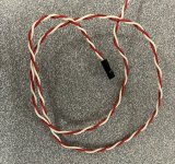
A shielded cable of this length and at audio frequencies is not very useful. A twisted pair is better and easier to work but the twists have to be tighter than what I see in your photos. You could also try with a a sheet of metal between the boards and the SMPS. Best would be to take a look at the signal with a scope.
@andrew: you have the voltages and currents wrote on the schematic here. This is the schematic of the P2 but it is the same as the version with a single pair of power transistor.
Have a nice week-end.
Stef.
Attachments
This week I'll finally test the Q17, if I'm happy with the sound I'll go for the Turbo 1 in black 2oz (PcbWay). Maybe today if time permits, ...
After reviewing the Tibi, I am very surprised that a Q17 with not very good distortion values can beat Class A amplifiers that have distortion values in the thousandths of an order of magnitude. I'd still be interested to know what SR the Q17 has with 2 pairs on the output 🙂
Personally, I think a big part of the quality of the bass base is the power supply itself. (Sufficiently sized transformers + extreme filtering capacity...)
Last edited:
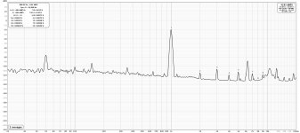
I'd still be interested to know what SR the Q17 has with 2 pairs on the output 🙂
I've done some measurement here for the Turbo.
The board was not in a box. Consider that these measures are preliminary. I'll redo measurement when the Turbo will be in a box.
Stef.
Attachments
Well, gentlemen, I am happy to say that the Q17 has not let me down at all. I tortured the amplifier for about 30 minutes into 4 ohms, with 35V power supply. The entire sound spectrum was beautifully presented, ...
I only listened to mono, so the sound experience wasn't perfect, but I dare say the Q17 will be better than my AUDIOLAB 6000A.
I made a sample video, but YouTube doesn't show all its qualities. I'm determined, I'm going to make a Q17 Turbo 1 (4pcb), and I'm going to fit it with the best parts I can buy...
Dual mono in modushop 4U box, 2x 500W toroidal transformers, + 80.000uF filtering per channel.
Have a nice rest of the weekend everyone! 😀
- Home
- Amplifiers
- Solid State
- Q17 - an audiophile approach to perfect sound