Hello ,
yes I have also already compared the three types: OPA165x, OPA164x and OPA161x compared, also on the Q17. The result is always the same:
the OPA1655 plays warmly soft to sweet and lets finest details disappear in the background of the music
the OPA1641 plays dynamically alive with a fine nuance of sounding
the OPA1611 plays ultra natural and very emotionally super fine resolving.
Regards Tim
Thanks for the feedback, Tim.
I was leaning towards the 1611 for this application but had very pleasant results using 1655 in a DIY DAC project.
I was leaning towards the 1611 for this application but had very pleasant results using 1655 in a DIY DAC project.
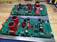
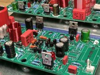
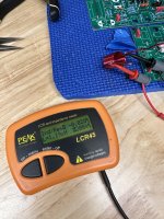
Opamp, drivers and OPS trans. not installed yet. Probably a good time to power up and confirm opamp psu section is working as it should.
I’ve got a dilemma now…..
Prepare food and cook for tomorrow’s holiday OR continue working on Q17 and possibly have a new working amplifier?? 🤣🥳
I’ve got a dilemma now…..
Prepare food and cook for tomorrow’s holiday OR continue working on Q17 and possibly have a new working amplifier?? 🤣🥳
Attachments


Probably a good time to power up and confirm opamp psu section is working as it should.
Hi Vunce,
Don't power on the board without opamp. The board will burn without opamp.
Stef.
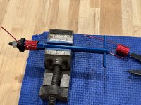
When you mount resistor, or any other THT part, it is good to keep at least 2mm distance from PCB.
Some parts dissipate power (as heat) and the PCB, in time, will burn.
Some parts dissipate power (as heat) and the PCB, in time, will burn.
Just to let you know that now JLCPCB offer teflon and Rogers PCB's.
Rogers is way to advanced, but teflon is something you may consider when aiming for the best and Q17 is one of the best amplifiers you will build in your lifetime. So, go for it. 😎
Rogers is way to advanced, but teflon is something you may consider when aiming for the best and Q17 is one of the best amplifiers you will build in your lifetime. So, go for it. 😎
When you mount resistor, or any other THT part, it is good to keep at least 2mm distance from PCB.
Some parts dissipate power (as heat) and the PCB, in time, will burn.
Right.
Resistors with a red cross must be detached from the PCB.
Stef.
Attachments

Tibi,Just to let you know that now JLCPCB offer teflon and Rogers PCB's.
Rogers is way to advanced, but teflon is something you may consider when aiming for the best and Q17 is one of the best amplifiers you will build in your lifetime. So, go for it. 😎
You're a great salesman.
It's also nice to see more discussion here in the post again, so some material to think about:
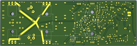
Now for the physical optimisation of circuit boards:
1. i don't understand how you can mount a coil orthogonally a few mm away from the radiator and clearly accept eddy current losses?
2) Why do we talk about very low internal resistances of MosFETs so that we can reduce the back inductions of the loudspeakers in the low bass as much as possible and design the amplifier for pulses for currents in the mid two-digit amperes and the circuit board for about 10% of these currents?
3) Why are there no large footprints and low-resistance tracks between the film capacitors and the components to be supplied? A small distance is laudable, but not everything.
4. why does nobody discuss the switch layout with regard to the positioning of the GND connections of individual components in the design?
Regarding 4. I have found in my experiments that for a noiseless 0 output, capacitor C2 needs to be placed near the input, while for the ground connection of R6 a position near R32 is advantageous.
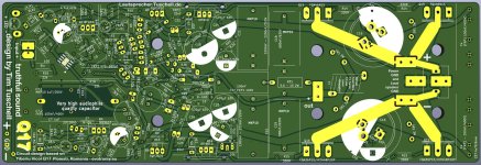
If it is known that C2 in physically large size brings sonic advantages over the small size, why are the small ones installed? A Teflon board is of no use, nor are gold layers between the solder and the copper conductor....
Before we ask about Teflon - which is of course to be avoided in terms of environmental impact - we should ask what is being soldered with? Not because of the resistance of the material, but because of its mechanical strength, because of the chemical connection quality... I don't read here a recommendation like: the eutectic alloy of tin solder with silver and copper content is: 95.5Sn 3.8Ag 0.7Cu and this has very good mechanical parameters. This would also be worth a contribution if it is a very good quality.
Otherwise, I wish you happy holidays, happy Easter
and still attached a contribution from me on the dual power amp (this is based on an excellent playing single setup and has not yet been built in the dual), in case anyone wants to try out another layout. (I add here my personal experiment findings: a single output sounds cleaner, more natural and deeper in bass control than a dual).
Regards Tim
Partslist: http://lautsprecher.tuschell.de/DIY/Q17/TeilelisteQ17-V13_X2.htm
Attachments
it looks like a 0-ohm componentI think there is another error on Vunce PCB. You can't see very well in the photos. Resistor R32 should be a strap not a resistor.
Stef.
No worries fellas!
-R32 is a 0R resistor.
-All resistors spec’ed above 1/2W are lifted from the pcb, maybe the angle of the picture is obscuring the real view.
-No need to lift ‘regular duty’ resistors.
(If that were the case, smd resistors could never be used)
Thanks for the heads up to install the opamp before power up! I wanted to confirm the front end psu section worked so the opamp didn’t get fried in case of error.
"100uf bipolar I would give better quality, (Audio Note Seiryu).
1, What capacitor will you use at position C7?
2, Will you be installing IXTH48P20P?"
HRDSTL,
I'll check out that Seiryu cap
1) Mundorf
2) FQA36P15
Before throwing upgrades at Q17, I want to make sure it's an amplifier that will be part of my collection.
1, What capacitor will you use at position C7?
2, Will you be installing IXTH48P20P?"
HRDSTL,
I'll check out that Seiryu cap
1) Mundorf
2) FQA36P15
Before throwing upgrades at Q17, I want to make sure it's an amplifier that will be part of my collection.
- Home
- Amplifiers
- Solid State
- Q17 - an audiophile approach to perfect sound