Hi Tibi,I want to update documentation too and I'm a bit slow with words.
Regards,
Tibi
If you want. I can proofread the docs for you to find the typos.
Regards,
Stef.
Thank you Stef, I have corrected this !
As soon I finish documenting, I'll send you a copy for review.
Regards,
Tibi
As soon I finish documenting, I'll send you a copy for review.
Regards,
Tibi
I procured the big mosfets for my damaged 1st channel and after replacing the amp works fine 🙂
I have also read Tibi's post of setting R25 to 2k2 ohm (I am using a +/-33vdc rails) and on one of the channel I made this change and now both the channels are up and running since few hours and making beautiful music. The amp sounds very good and I feel something different to my class A taste in a good way though 😉
Will do the R25 change on the other channel too in next few days and run with my Troels + HPA1 combo paired with the Soekris 1021 in my main setup replacing my J2 clone.
thanks
Very happy for you that you eventually succeeded in getting MUSIC out of the machine! And even more that you like what you hear, that is where it's all about....I procured the big mosfets for my damaged 1st channel and after replacing the amp works fine 🙂
I have also read Tibi's post of setting R25 to 2k2 ohm (I am using a +/-33vdc rails) and on one of the channel I made this change and now both the channels are up and running since few hours and making beautiful music. The amp sounds very good and I feel something different to my class A taste in a good way though 😉
Will do the R25 change on the other channel too in next few days and run with my Troels + HPA1 combo paired with the Soekris 1021 in my main setup replacing my J2 clone.
thanks
I am busy with my amp, Tibi's pcb, so the same as yours. There is regrettebly a litlle quirk in the gerber, the Q5 and the Q6 are placed just outside the board.
I will try to get them connected as is though. I could not find the correct Gerber, when I looked just now and I don,t fancy waiting another three weeks to get new peeceebees!
Will have all the parts complete this week I expect. In the meantime I did put the power supply together including the tht Saligny standard, 50 Volts.
B.t.w why did you use a +- 33Volt rail?
Have fun,
Ed.
Thanks Ed, I do not have any issues on the Q5/6 placement on the pcb and I have mounted all the mosfets on the heat sinks for thermal equilibrium as they say but not sure how much thats important though. I used the TO-220 plastic bushes for all the 220 mosfets to isolate them from the metal heat sinks and also used a silicon pad and some grease. My pcb had issues with the output speaker connector pads which Tibi pointed out and I had to cut traces around the pad in 3 places to isolate the + speaker binding post pad from the ground plain. And then I had to short the - speaker ground post to the DC ground pin as it was floating.Very happy for you that you eventually succeeded in getting MUSIC out of the machine! And even more that you like what you hear, that is where it's all about....
I am busy with my amp, Tibi's pcb, so the same as yours. There is regrettebly a litlle quirk in the gerber, the Q5 and the Q6 are placed just outside the board.
I will try to get them connected as is though. I could not find the correct Gerber, when I looked just now and I don,t fancy waiting another three weeks to get new peeceebees!
Will have all the parts complete this week I expect. In the meantime I did put the power supply together including the tht Saligny standard, 50 Volts.
B.t.w why did you use a +- 33Volt rail?
Have fun,
Ed.
I already have a 22VAC 6.8A 300VA trafo from my MyRef build which I reused along with the spare CRC psu board using LT4320 and I have shorted the Rs as Tibi suggested being a class B it might oscillate.
manniraj,
Glad to hear you like the amplifier ! This is all that matters.
This make easy to mount and service.
Regards,
Tibi
Glad to hear you like the amplifier ! This is all that matters.
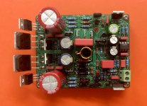
These transistors have been intentionally mounted on the edge of the PCB with castellated holes....
I am busy with my amp, Tibi's pcb, so the same as yours. There is regrettebly a litlle quirk in the gerber, the Q5 and the Q6 are placed just outside the board.
...
This make easy to mount and service.
Regards,
Tibi
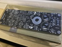
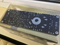
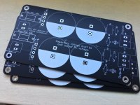
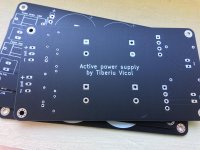
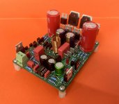
Attached pictures are with 2pair Q17 and his active power supply.
On the 2 pair PCB I have pushed all heatsink transistors to castellated holes an it was quite difficult to design such way.
Regards,
Tibi
On the 2 pair PCB I have pushed all heatsink transistors to castellated holes an it was quite difficult to design such way.
Regards,
Tibi
Attachments

That's just me! On hindsight I understand how clever it is to mount the fets that way, easy to replace, though I hope this will never be needed. Did not understand what 'castellated holes' meant, but now I know. Thanks for the clear clarification!Attached pictures are with 2pair Q17 and his active power supply.
On the 2 pair PCB I have pushed all heatsink transistors to castellated holes an it was quite difficult to design such way.
Regards,
Tibi
Regards.
Are these new pcbs that you have printed? Very clever idea of easily replaceable FETs 🙂Attached pictures are with 2pair Q17 and his active power supply.
On the 2 pair PCB I have pushed all heatsink transistors to castellated holes an it was quite difficult to design such way.
Regards,
Tibi
Yes, these are new PCB's.
I have short moments when I'm clever, but this time just copied from Accuphase.
Regards,
Tibi
I have short moments when I'm clever, but this time just copied from Accuphase.
Regards,
Tibi
Hi TibiAttached pictures are with 2pair Q17 and his active power supply.
On the 2 pair PCB I have pushed all heatsink transistors to castellated holes an it was quite difficult to design such way.
Regards,
Tibi
For listening on moderate, a not really loud listening like I do, wich setup would you prefer. One or two power fets?
Hi Tibi again...
In the manual of the active powersupply I read one can skip C5/R3 and C6/R4,
In the BOM I see your advise to 'strap' them. In my understanding, this means 'bridge them?
My idea is,: when the filter is not needed, than don't put both capacitor and resistor on the board, so skip them and don't make any connection.
What can you say? I am a bit puzzled.
Regards,
Ed
If you use high SPL, easy to drive speakers, one pair is enough. One pair of Fairchild's is able to drive my Dynaudio's better than 8 pairs of laterals.
If you use low SPL speakers with complex crossovers, than 2 pairs will drive them.
The level of listening does not matter.
On active power supply, R3,R4,C5,C6 are not needed if you use Saligny rectifiers.
Regards,
Tibi
If you use low SPL speakers with complex crossovers, than 2 pairs will drive them.
The level of listening does not matter.
On active power supply, R3,R4,C5,C6 are not needed if you use Saligny rectifiers.
Regards,
Tibi
Hello folks,
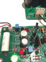
The new 1.2 version of my Q17-Mini is working. For the moment, I just tested it with 30Vdc. I got 32mV of output offset and 7mVRMS of noise. Sinus and Square on scope seems ok.
I must made more testing at 50Vdc with measures now.
The files on my GitHub repository are not yet updated for 1.2.
Have a nice week-end.
Stef.
Abstract for Q17-Mini 1.2:
- New LPF (R33/C20/R22) at input to protect op-amp.
- L1 coil is now positioned vertically and have more space around.
- Q7 and its resistors moved to a better location.
- New gate stopper resistor R40/R41 for Q1 and Q4.
- R32 moved to a better location.
- New C7 footprint can fit Wima MKP2, FKP2 and MKS4 (5mm and 7.5mm pitch).
- C17 now can fit Wilma FKP3 and MKP10.
- New C20 can fit Wima FKP2, Vishay MKT and CDE Mica (5mm and 5.9mm pitch).
- New design for 70% of tracks. Removed all signal VIAS (there were eight).
- Ground plane on both sides with ground VIAS.
- Added some optional SMD footprints on the back side.
- More silkscreen text on back side.
Attachments
Last edited:
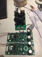
Hi all!
As you can see, all the work is done. Exept.......this dummie ordered the wrong size opa1641! En I can not find a 1641AIDR or a 1655D.....(SOIC8).
Maybe someone here in europe, (Netherlands), can make me happy with a pair of left-overs? So the the music can start.
Looking forward,
Ed
As you can see, all the work is done. Exept.......this dummie ordered the wrong size opa1641! En I can not find a 1641AIDR or a 1655D.....(SOIC8).
Maybe someone here in europe, (Netherlands), can make me happy with a pair of left-overs? So the the music can start.
Looking forward,
Ed
Attachments


Hello,
I uploaded the new files for Q17-Mini-1.2.
I have some spare PCBs if anyone is interested.
For Ed: Digikeys still have some OPA1641 SOIC-8 in stock : https://www.digikey.fr/fr/products/detail/texas-instruments/OPA1641AID/2202256
Mouser, RS-Components and Farnel are out of stock.
Regards,
Stef.
I uploaded the new files for Q17-Mini-1.2.
I have some spare PCBs if anyone is interested.
For Ed: Digikeys still have some OPA1641 SOIC-8 in stock : https://www.digikey.fr/fr/products/detail/texas-instruments/OPA1641AID/2202256
Mouser, RS-Components and Farnel are out of stock.
Regards,
Stef.
Hello again,
I made a test with R32 value change with the new PCB (still at 30vDC).
If R32 = 10R, I got 32mV of output offset. If I change R32 to 5R (2 x 10R in parallel), I got 18mV of output offset. Not tried below yet.
Do you have an explanation for this?
Stef.
I made a test with R32 value change with the new PCB (still at 30vDC).
If R32 = 10R, I got 32mV of output offset. If I change R32 to 5R (2 x 10R in parallel), I got 18mV of output offset. Not tried below yet.
Do you have an explanation for this?
Stef.
- Home
- Amplifiers
- Solid State
- Q17 - an audiophile approach to perfect sound