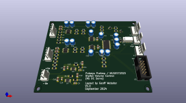
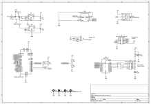
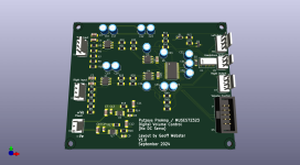
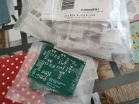
As discussed a few posts ago, here's the version with TPS7A4901/3001 ultra low noise LDOs onboard:

I've also looked up techniques for soldering these LDO devices which have a thermal pad underneath the body as well as the usual pins along two sides. It seems that, provided you have a corresponding solder pad on the underside of the boards with vias between these top and bottom thermal pads, they are relatively straightforward to hand solder. Dave Jones over at EEVblog has a good video demonstrating how to do it.
If there's interest, I'll post the Gerbers and BOM for them. For those that this might be a step too far, I'll also post Gerbers and BOM for the board without the extra bells and whistles.
Agreed, those are easily hand soldered. Those are used on the UGS Muse preamp here on diyaudio, and were no problem. I used my Hakko 936 with a 3.2mm chisel tip for the thermal pad. Conversely the TPS7A4700/TPS7A3301 in the VQFN-20 package is a nightmare to attempt. I tried some of these on a board (3 oz. copper) and could not do it, even with a hot air gun.
Geoff, thank you for your effort.
Would it be possible to design one board with both options?
Wire jumper (regulator bypass) could be used in case user would like to use external supply over X4 connector.
What do you think?
Would it be possible to design one board with both options?
Wire jumper (regulator bypass) could be used in case user would like to use external supply over X4 connector.
What do you think?
In actual fact, to bypass use of the two LDOs, simply don't fit any of the LDO and associated Rs and Cs thenWould it be possible to design one board with both options?
Wire jumper (regulator bypass) could be used in case user would like to use external supply over X4 connector.
What do you think?
- wire a link from C7 (pad connecting to X4 pin) to C11/R14 pad
- wire a link from C10 (pad connecting to X4 pin) to C12/R16 pad
Hello Geoff,
This is a great project and thanks for sharing it to the community. Do you have the schematic with the arduino Nano? If so can you share it. Thanks in advance.
Nof
This is a great project and thanks for sharing it to the community. Do you have the schematic with the arduino Nano? If so can you share it. Thanks in advance.
Nof
Hello Geoff,
This is a great project and thanks for sharing it to the community. Do you have the schematic with the arduino Nano? If so can you share it. Thanks in advance.
Nof

There you go! In my application and the remote handset I use (uses RC-5 protocol and is originally foran Arcam amplifier/tuner), the IR receiver is a 36KHz one.
Here are the Gerbers and a bare bones BOM ( no Mouser part nos as yet). I'll add them shortlyAs discussed a few posts ago, here's the version with TPS7A4901/3001 ultra low noise LDOs onboard:
View attachment 1353127
I've also looked up techniques for soldering these LDO devices which have a thermal pad underneath the body as well as the usual pins along two sides. It seems that, provided you have a corresponding solder pad on the underside of the boards with vias between these top and bottom thermal pads, they are relatively straightforward to hand solder. Dave Jones over at EEVblog has a good video demonstrating how to do it.
If there's interest, I'll post the Gerbers and BOM for them. For those that this might be a step too far, I'll also post Gerbers and BOM for the board without the extra bells and whistles.
Attachments
Geoff, minor (really minor) comment: On the bottom silkscreen one capacitors is without label, also location on label "C29" probably needs adjustment.
Nothing important, easy to live with it.
Nothing important, easy to live with it.
Since we a commenting, i would suggest a large hole, 1.5mm/0.8 PAD at centre of each regulator IC will facilitate a lot the soldering of them.
I have used this solution many times and it is easy to solder like that.

I have used this solution many times and it is easy to solder like that.
Last edited:
Oh shucks, I'll correct those and repost the Gerbers when I've put part numbers into the BOMGeoff, minor (really minor) comment: On the bottom silkscreen one capacitors is without label, also location on label "C29" probably needs adjustment.
Nothing important, easy to live with it.
Another simple thing to do is apply light layer of solder to the top layer of the heatsink pad then plenty of flux. When heat is applied via a reasonable size chisel tipped soldering iron to the bottom heatsink pad, all should reflow with no real problem and simply ensure the pins are properly aligned before removing heat.Since we a commenting, i would suggest a large hole, 1.5mm/0.8 PAD at centre of each regulator IC will facilitate a lot the soldering of them.
I have used this solution many times and it is easy to solder like that.
Attachments
Last edited:

Posts relating to programming and coding for this are split off here:
https://www.diyaudio.com/community/...d-preamplifier-with-muses72323-volume.417517/
Not too worried about it. Both are on my list to use. If I really had to, I'd get the solder paste and heat gun outFlux (and leaded solder) would be your friends here...
I normally use liquid flux, and found it to be very useful in clearing bridged pins on much finer pitch devices than these (with desoldering braid). I doubt that you will need to resort to the heat gun.
That's much the same technique I use. I often don't need de-soldering braid as drag soldering works well in conjunction with the flux.I normally use liquid flux, and found it to be very useful in clearing bridged pins on much finer pitch devices than these (with desoldering braid). I doubt that you will need to resort to the heat gun.
To be honest, my main use of a heat gun is where I want to remove a component potentially for reuse or when replacing a duff one. 😉
It'll be interesting to see how easy soldering the LDOs will be.
Very easy:
This is from a discussion in one of the threads on Digital Line Level.
Alex.
The video says "Easy" at the beginning but seems to make a meal of a relatively straightforward procedure by doing half of the steps twice. There are much easier ways of doing it 😉.This is from a discussion in one of the threads on Digital Line Level.
The chip style we're putting down is much easier anyway. I'll be doing it later today. Let's see how it goes.
- Home
- Source & Line
- Analog Line Level
- Putzeys Balanced Preamplifier with MUSES72323 Volume

