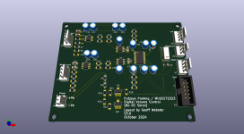
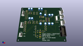
I don't have issues with LDOs per se but when I have a perfectly good low noise PSU feeding the board anyway I don't see the need for the on-board ones as well. Especially when I'm seeing pretty quiet supply rails and analogue outputs without them. There's such a thing as overkill.Frankly i don't see why you have issues with the LDO's but those have limited current capability
Last edited:
From a board rework point of view, the location of the electrolytics between the MUSES chip and the relay makes any necessary touch-up of solder joints on the MUSES pins that are alongside the electrolytics very difficult.
If I were to go further with the board, I would
- Delete the on-board regulation
- Consider provision for off-board control of the muting relay (e.g. taking a MUTE signal from a microcontroller)
- Relocate the electrolytics to provide reasonable access to the MUSES pins so as to enable easier rework of its device pin solder joints

That would work out like this
Attachments
Sometimes life gets in the way of moving forward with things but finally here is the current version which implements all of the above.From a board rework point of view, the location of the electrolytics between the MUSES chip and the relay makes any necessary touch-up of solder joints on the MUSES pins that are alongside the electrolytics very difficult.
If I were to go further with the board, I would
- Delete the on-board regulation
- Consider provision for off-board control of the muting relay (e.g. taking a MUTE signal from a microcontroller)
- Relocate the electrolytics to provide reasonable access to the MUSES pins so as to enable easier rework of its device pin solder joints

I have 5 spare boards going if you're in the UK
Attachments
Never having tried it, the simple answer is that I don't know.Hi geoffw1, based on your latest schematic, if I only need pure volume control, what should the actual schematic look like? Should I remove the four op amps in the schematic?
As a minimum, especially if you aren't interested in maintaining a balanced input, I would suggest that it would be worth hanging onto the last op amp in each channel and using the the two halves as simple unity gain non-inverting buffers.