There are much easier ways of doing it
There are many ways.
For example, order a stencil, apply the soldering paste, install the chip and put everything in the oven.
I sometimes do this, but for the entire board and not for a separate chip - a separate one is easier for me with a hot air blower.
Or you can order both the board and the parts in JLC, and have them all soldered.
Alex.
Last edited:

Not so difficult doing the LDOs. I pre-tinned the thermal pad on the board, applied a load of liquid flux, then used a heat gun with the airflow set low ( having it higher blew the LDO off the board) and finally drag soldered the pins. Pity I forgot to order the 10uF chip capacitors so I need to wait till I get them before I can test it all😕

It saved you the trouble of losing them on the floor...Pity I forgot to order the 10uF chip capacitors
Nah, they're bl***y huge compared to what I'm used to😉 When I retrieve my stash of capacitors off my son who borrowed them to fault-find his guitar preamp, I'll tack something sensible in their place while I check it all outIt saved you the trouble of losing them on the floor...
@geoffw1 great project with the Muses volume chip. Is there a way to use this board without the preamp section like say people already having preamps but would like to add the Muses chip? Having that option or a new pcb with only the Muses chip and its associated circuit will make it versatile.
Thanks
Thanks
It would be possible to miss out all the active elements around the Muses chip excepting coupling / decoupling capacitors and fit links to provide connections from the input connector to the Muses chip and from the Muses chip to the output connector. However, as the circuit currently is, the initial stages provide a 0dB buffer before the attenuator resistive chain and the final stage, when run in the Muses default gain setting (0dB), does the same for the output.@geoffw1 great project with the Muses volume chip. Is there a way to use this board without the preamp section like say people already having preamps but would like to add the Muses chip? Having that option or a new pcb with only the Muses chip and its associated circuit will make it versatile
10uF capacitors now fitted and new board with relay and ultra-low noise LDOs fired up. Abject failure as +/- rails measured 1.26V. Looking at the schematic soon showed this week's deliberate mistake - voltage divider resistors between the voltage output, V-feedback pin and ground were the wrong way round. Swapping them over resulted in +V rail now being +14.99V but the -V rail is just not working at all. I can't get any more diagnosis done today as it's the wife's birthday so need to open the odd bottle of fermented grape juice. More soonPity I forgot to order the 10uF chip capacitors so I need to wait till I get them before I can test it all😕
🍷🍷🍷🍸🍸🍸
Reseating the -ve LDO succeeded in getting a negative voltage on the board However, it was the same voltage as the input. Checking all joints, component values and chip alignment didn't achieve anything so the end result was removing both LDOs and associated components then fitting links in their place.V-feedback pin and ground were the wrong way round. Swapping them over resulted in +V rail now being +14.99V but the -V rail is just not working at all.
Next discovery was that the diode across the coil winding was fitted correctly according to the schematic / layout but in fact was reverse polarity. This prevented the relay from opening causing no output from the pre-amp. Swapping the diode round appeared to resolve this and the relay now opened the contact across the pre-amp outputs. Switching the power off/on to verify correct muting doesn't yet seem to provide correct muting on switch-off so needs more investigation.
Hi Geoff!
Please correct or confirm, which pins of MUSES72323 and ESP32 controller belong together.
MUSES DATA = ESP32 GPIO23
MUSES CCLK = ESP32 GPIO18
MUSES LATCH = ESP32 GPIO5
Thank You!
Please correct or confirm, which pins of MUSES72323 and ESP32 controller belong together.
MUSES DATA = ESP32 GPIO23
MUSES CCLK = ESP32 GPIO18
MUSES LATCH = ESP32 GPIO5
Thank You!
Investigations now completed and highlight a few issues with the relay circuitReseating the -ve LDO succeeded in getting a negative voltage on the board However, it was the same voltage as the input. Checking all joints, component values and chip alignment didn't achieve anything so the end result was removing both LDOs and associated components then fitting links in their place.
Next discovery was that the diode across the coil winding was fitted correctly according to the schematic / layout but in fact was reverse polarity. This prevented the relay from opening causing no output from the pre-amp. Swapping the diode round appeared to resolve this and the relay now opened the contact across the pre-amp outputs. Switching the power off/on to verify correct muting doesn't yet seem to provide correct muting on switch-off so needs more investigation.
- Schematic and layout have pins 2 and 3 of the relay, and consequently the right channel output, connected to ground 🙄
- With the dc input voltages at +/-18V or thereabouts, the relay driver transistor dissipation exceeds the device spec 🙄
MUSES Data ESP32 MOSI=23 (GPIO23)Hi Geoff!
Please correct or confirm, which pins of MUSES72323 and ESP32 controller belong together.
MUSES DATA = ESP32 GPIO23
MUSES CCLK = ESP32 GPIO18
MUSES LATCH = ESP32 GPIO5
Thank You!
MUSES CCLK ESP32 SCLK=18 (GPIO18)
MUSES LATCH ESP32 s_select_72323 = 16 (GPIO16)
In my ESP32 implementation of the controller for the MUSES72323, the SPI bus is used by a few other devices besides running the MUSES chip, so different select pins are used to select each of these, the MOSI/MISO/SCLK pins being common to all of them.
These are
- MUSES72323 - GPIO16
- TFT display - GPIO5
- TFT Touch - GPIO25
- MCP23S08 - GPIO10
- IR receiver - GPIO27
- Rotary encoder
- Rotary A - GPIO33
- Rotary B - GPIO32
- Rotary switch - GPIO12
Where does the ESP32 MUTE pin (GPIO17) connect?MUSES Data ESP32 MOSI=23 (GPIO23)
MUSES CCLK ESP32 SCLK=18 (GPIO18)
MUSES LATCH ESP32 s_select_72323 = 16 (GPIO16)
In my ESP32 implementation of the controller for the MUSES72323, the SPI bus is used by a few other devices besides running the MUSES chip, so different select pins are used to select each of these, the MOSI/MISO/SCLK pins being common to all of them.
These are
In my implementation of a controller , other peripherals connected to the ESP32 are
- MUSES72323 - GPIO16
- TFT display - GPIO5
- TFT Touch - GPIO25
- MCP23S08 - GPIO10
- IR receiver - GPIO27
- Rotary encoder
- Rotary A - GPIO33
- Rotary B - GPIO32
- Rotary switch - GPIO12
That was used by my previous Putzeys/Digital volume control board that used an MAS6116. This is a similar device to the MUSES 72323 but also has a separate Mute input as well as the SPI stuff. When I saw the MAS6116 was going EOL, it prompted me to have a look at working with the latest of the MUSES chips i.e. this MUSES72323.Where does the ESP32 MUTE pin (GPIO17) connect?
Applying lessons learned from the previous board with ultra-low noise LDOs + output mute relay circuit, amendments to the board are
- provision for bypass links if not using the ultra-low noise LDOs
- removal of incorrect ground connections across right output feeds
- addition of dropper resistor between relay coil and enabling transistor to cater for higher supply rail voltages (select the value to present 12V across relay coil)
- replace original relay drive transistor for higher wattage device
- increase size of vias in heatsink pads of ultra-low noise LDO footprints (aid in solder transfer during assembly)
Attachments
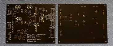
Boards now arrived and built.
Firstly, the ultra-low noise LDOs were assembled with a few solder reflow required before +/-15V was achieved. The rest of the circuit was then assembled and tested.
First issue was that the +15V rail had shut down and the -ve LDO was running very hot. After a few goes at trying to get the supplies working correctly, the on-board regulation was removed and the bypass links fitted instead.

As previously, the pre-amp/volume control sections worked exactly as expected. It should be noted that the pre-amp outputs are very clean and I would suggest that provided a decent low noise regulated supply is feeding the board, the on-board regulation is not needed.
As far as the muting circuit goes, on power-off, the mute relay was not switching fast enough to short out the output and prevent potential speaker thump. Use of LTSpice showed that significantly reducing the value of R13 from 2K2 down to between 120R and 470R would enable the muting circuit to trigger at voltages much closer to the applied supply voltages. The resistance value to be used would therefore require selection so that the muting occurs with only a small dip in the power rail voltage. For +/-18V this would be around 120R. For +/-12V, this would be the original Putzeys G-Word circuit value of 2K2.
From a board rework point of view, the location of the electrolytics between the MUSES chip and the relay makes any necessary touch-up of solder joints on the MUSES pins that are alongside the electrolytics very difficult.
If I were to go further with the board, I would
Firstly, the ultra-low noise LDOs were assembled with a few solder reflow required before +/-15V was achieved. The rest of the circuit was then assembled and tested.
First issue was that the +15V rail had shut down and the -ve LDO was running very hot. After a few goes at trying to get the supplies working correctly, the on-board regulation was removed and the bypass links fitted instead.
As previously, the pre-amp/volume control sections worked exactly as expected. It should be noted that the pre-amp outputs are very clean and I would suggest that provided a decent low noise regulated supply is feeding the board, the on-board regulation is not needed.
As far as the muting circuit goes, on power-off, the mute relay was not switching fast enough to short out the output and prevent potential speaker thump. Use of LTSpice showed that significantly reducing the value of R13 from 2K2 down to between 120R and 470R would enable the muting circuit to trigger at voltages much closer to the applied supply voltages. The resistance value to be used would therefore require selection so that the muting occurs with only a small dip in the power rail voltage. For +/-18V this would be around 120R. For +/-12V, this would be the original Putzeys G-Word circuit value of 2K2.
From a board rework point of view, the location of the electrolytics between the MUSES chip and the relay makes any necessary touch-up of solder joints on the MUSES pins that are alongside the electrolytics very difficult.
If I were to go further with the board, I would
- Delete the on-board regulation
- Consider provision for off-board control of the muting relay (e.g. taking a MUTE signal from a microcontroller)
- Relocate the electrolytics to provide reasonable access to the MUSES pins so as to enable easier rework of its device pin solder joints
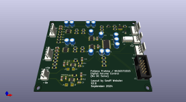
If someone would like to give it a try, I can share the board.
I've ordered 10, 3 are to stay with me so 7 can go.
ENIG and black finish.
I think 4.00 Euro per board is fair.
Shipping across EU is like 6.00 to 7.00 Euro (economy, traceable).
PM me if interested.
I've ordered 10, 3 are to stay with me so 7 can go.
ENIG and black finish.
I think 4.00 Euro per board is fair.
Shipping across EU is like 6.00 to 7.00 Euro (economy, traceable).
PM me if interested.
Attachments
😱😱😱This is Ver 1.0 of the board - it has error on the relay pins such that right output is permanently shorted out. To remove the short circuits on this version 1.0 requires to cut through the ground plane around pin 2 and pin 3 of the relay.If someone would like to give it a try, I can share the board.
I've ordered 10, 3 are to stay with me so 7 can go.
ENIG and black finish.
I think 4.00 Euro per board is fair.
Shipping across EU is like 6.00 to 7.00 Euro (economy, traceable).
PM me if interested.
Version 2 (which I'm testing at the moment corrects this along with a few other mods (see posts #94 and #95 above).
Last edited:
I know, it was ordered like three weeks ago.
I am not about to use relay here, I assume users here are aware of these issues.
I am not about to use relay here, I assume users here are aware of these issues.
You still need to cut the ground plane away from those pins as they form a direct short across the output for the right channel. Everything else works fine.I am not about to use relay here, I assume users here are aware of these issues.
- Home
- Source & Line
- Analog Line Level
- Putzeys Balanced Preamplifier with MUSES72323 Volume