Thanks a lot for providing this very informative paper! I'll have to translate his proprietary values into more convenient metric units, though 😆.
Sadly, he didn't tell exactly how he prevents the wire from slipping when approaching the layers' ends.
Best regards!
Sadly, he didn't tell exactly how he prevents the wire from slipping when approaching the layers' ends.
Best regards!
New experiments with this amplifier:
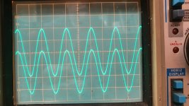
I connected g2 to anode (triode mode) and the spurious oscillation stopped. Cathode feedback is still in place. However, I see badly distorted waveform on 8 ohm load at 1 kHz and above. 100 Hz is about acceptable. See the signals on the anodes. Horizontal: 0.2 ms/div, Verical: 50 V/div. Input signal: 1 kHz / 2.2 Vrms. The driving signal on the 807s' g1 is perfectly clean. Could it be due to the leakage or stray capacitance in the output transformer?
I connected g2 to anode (triode mode) and the spurious oscillation stopped. Cathode feedback is still in place. However, I see badly distorted waveform on 8 ohm load at 1 kHz and above. 100 Hz is about acceptable. See the signals on the anodes. Horizontal: 0.2 ms/div, Verical: 50 V/div. Input signal: 1 kHz / 2.2 Vrms. The driving signal on the 807s' g1 is perfectly clean. Could it be due to the leakage or stray capacitance in the output transformer?
Attachments

In #24 Bigun advised to swap the cathode leads. Your symptom may be attributed to PFB into the cathodes instead of NFB.
Re your question in #54: Swap both middle primary packs in your split bobbin transformer. Obey correct phasing when doing this. Swapping secondary parts won't be as effective.
Best regards!
Re your question in #54: Swap both middle primary packs in your split bobbin transformer. Obey correct phasing when doing this. Swapping secondary parts won't be as effective.
Best regards!
Could you trace the grid signal and the cathode signal on the two traces with 0V in the same place please.
Actually, I'm feeling a bit ripped off here. I did it first, and described it in this thread: Tee Vee Toob Amp. I looked at SSassen's thread and he makes out like he thought of this himself. Maybe he did, and maybe he didn't, I don't know. It's still a possibility he saw my thread and took credit where credit is not due. In that thread, he admits:Credit goes to SSassen for the cascoded LTP phase splitter idea:
Alright, I've made a few posts in the last few weeks as I'm working on a new tube amplifier design and am very appreciative of all the replies and suggestions I've gotten, thanks again for that! This morning I figured that one trick I hadn't yet tried to further reduce distortion and up the gain on the input stage is to simply cascode it. Seems straightforward enough right?
Well, a mere hour or so after I made the changes in my schematic I felt I had a pretty good handle on things and ran some simulations. The results were everything I hoped for, frankly quite a bit more than that. Thinking I must've done something wrong somewhere I've double checked everything and even tossed in some transistors instead of the triodes to see whether that would give the same results and low and behold it did.
Can any of you fine gentlemen perhaps let me know whether I'm being an complete and utter idiot here, or whether I fail to understand a mechanism at play here that would yield such excellent results? But before you answer that question let me quickly give you a circuit description.
(You fail to understand. The reason the hollow state audio cascode works so well is the same reason why it's done all the time in solid state designs: you divide the output swing across two devices instead of one. Getting a transistor's vce down does the same thing as minimizing vpk. That's where I got the idea to cascode 6BQ7's for the Lr Renard project: from the solid state designs I did.)
The LTP is pretty straightforward, as is the cascode, but for the additional transistor Q1 which does double duty, it acts as a constant current source and tightly controls the AC balance of the LTP which pretty much depends on how closely matched the 1Meg resistors are and no longer how well matched the two triode sections are.
(Emphasis mine)
I suspect that I'm not the only one being ripped off. That part I emphasized? That idea came from CarLOS (no longer active). It was discussed at length at his old forum (no ,longer active).years ago. The ultimate consensus was that it wasn't really worth the bother unless you had some spectacularly mismatched triode sections, or were using lowish u-Factor tubes like the 6SN7 as an LTP.
I admit not having done research about the origin of cascoded LTP. I just mentioned where my inspiration came from. It's a pity I haven't seen Le Renard sooner, it would have saved me a lot of headache.Actually, I'm feeling a bit ripped off here. I did it first, and described it in this thread: Tee Vee Toob Amp.
I double checked the cathode feedback signal polarity, it is opposite to g1 like it should be. The output signal is distorted only when 8 ohms load is applied. It is clean without any load. And it is distorted asymmetrically, I wonder why.In #24 Bigun advised to swap the cathode leads. Your symptom may be attributed to PFB into the cathodes instead of NFB.
Re your question in #54: Swap both middle primary packs in your split bobbin transformer. Obey correct phasing when doing this. Swapping secondary parts won't be as effective.
Best regards!
Cathode feedback should be the same polarity as the grid, to be negative.
All good fortune,
Chris
All good fortune,
Chris
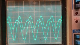
Here are the signals without and with dummy load. Upper trace: signal at the cathode of one tube, 5V/div. Lower trace: signal at the g1 of same tube, 20V/div. Input DC coupled. The CFB is indeed the same polarity as the grid signal. I can get similar waveform in LTSpice when I increase leakage and/or self capacitance of the trafo.Could you trace the grid signal and the cathode signal on the two traces with 0V in the same place please.
Attachments
Thats good to know. I guessing the kick is when the opposite tube goes out of conduction and the current in that half of the primary gets to zero. If you can replicate in LTspice you some way to understanding the issue. If you were to use a separate FB winding does it occur.
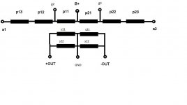
I experimented with the primary and secondary connections. The definitive best connection is: p11-p12-p13 in series (also the other chamber p21-p22-p23), B+ is connected to the inner coil. s11 and s22 connected parallel (also s21 and s12). See attached drawing.My transformer also has two chambers. In each chamber the winding sections are P1-S1-P2-S2-P3. All windings in a section belong to the same tube. P1-P2-P3 are connected in series, S1-S2 are connected parallel. Would it be better to interleve P1-S1'-P2-S2'-P3 where S1' and S2' are from the other chamber? Or some other mix?
The previous problems were caused by incorrect connection of the secondaries (s11 || s12 and s21 || s22). That connection caused loose coupling between the primary and secondary, resuting in high leakage inductance, oscillation, asymmetrical distorted waveform.
Now I restored the CFB and UL, everything is stable and the waveform is nice 🙂
Attachments


Exactly. The upper cutoff frequency at full output (about 15W @ k=1%) is 75kHz. Now I will listen to it as it is now, and then apply GNFB as you advised earlier.Excellent so you've mixed the secondary so each side comes from both primaries whereas before each side only came from one primary.
It sings! I listened to it quickly, the sound became 3-dimensional with depth (compared to LM1875 that I have used until now).
If you want a bit more output power I would recommend some 6550s but you may be quite happy as it stands.
Isn't the output power a matter of Eb voltage and primary impedance rather than the finals'?If you want a bit more output power I would recommend some 6550s but you may be quite happy as it stands.
Best regards!
- Home
- Amplifiers
- Tubes / Valves
- Push-pull 807 amplifier without global NFB