CF can be DC-coupled to 807 grid. Just need an additional negative voltage rail capable of providing enough current for CFs. Coupling capacitors go in front of CFs.
I second that. To get just 10 watts output power, a single 6L6GT/5881/807 in SE is sufficient. With PP arrangements, this is in the ballpark of 6V6's/6BQ5's or even smaller tubes.Those are big tubes ( like 6L6 ) , for just 10W is a wasteB+ should be much higher than "below 400V " .
Then you would need a good driver and eventually cathode followers
With 807's, class AB2, grid current and cathode followers make sense at higher plate voltages than just 400 V.
Best regards!
Today I turned on the actual amplifier, and wanted to measure around, but there is oscillation in the output stage. I have 820R at g1 and 680R at g2, and also a ferrite on the anode lead. The oscillation remains if I remove the other tubes. What do you recommend? A ferrite bead at g1 perhaps? Or increase the resistor at g2 to 2.2k or more?
Member
Joined 2009
Paid Member
Shot in the dark - try reversing the cathode feedback, just in case you have positive instead of negative feedback
Member
Joined 2009
Paid Member
This is a nice design. I have made myself a chassis to build something that is very similar. I think the main difference is that I am not planning to cascode the LTP because I will run the amp open-loop and don't need more gain. Otherwise very similar, cap coupled CF drivers - yes, seems to be a stupid idea on the face of it but it makes for a simpler psu and I'm trying to keep it simple. I'll post my stuff separately when I'm ready but wanted to say that you are not alone treading this path 🙂

I will try removing the resistor at g1 so that the output tube sees lower drive impedance from the CF.
Member
Joined 2009
Paid Member
You could try a 100n across the CF, on the base from anode to cathode, might need a different value if roll off of HF is too much. You could also try an 100r on each 807 top cap as well as an RC from anode to ground like shown on this schematic (C17/18 R55/56), see attached. These are all fixes with no idea of actual oscillation frequency , better to do a frequency sweep of your front end and CF drivers 10hz to 100khz or higher looking for peaks at certain frequencies with increased distortion, then fit LPF where needed. When your front end and drivers are stable repeat for whole amplifier.
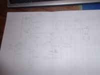
I'm building an 807 amp, considered a cascode or differential cascode with direct coupled CF's, in the end I've kept it relatively simple, DET20 with active anode load and 6BL7 LTP with CCS which can drive four 807's at twice G1-G1, see schematic. You'll see A paralleled 6SN7 as the front end, changed to single DET20, OP gain nearly the same at 18.5.
Good luck, Andy.
Attachments

C21/22 and R62/63 you mean? Anyway this is too complex for me, but there are some ideas to pick from. Please shae your experiences with yor build.
Try the output stage with the 807 cathodes not going through the OPT initially. What frequency is the oscillation?
Global negative feedback does help indeed. I attached the original and the feedback version, and the Fourier components compared. I will try both in the actual circuit. I am most interested in the stabilty and the audible difference.That I am afraid. So sorry...View attachment 1034449
Attachments
I have seen many ltp phase splitters before including cascoded, so why the credits for Ss? Nothing new here.Credit goes to SSassen for the cascoded LTP phase splitter idea:
Cascoded 12AX7 LTP - Stupid good performance?
and to Ite for his LTspice hierarchical ultralinear OPT model
OK, then I got the inspiration from his design. There is nothing new in tube circuits indeed, just clever application of existing knowledge.I have seen many ltp phase splitters before including cascoded, so why the credits for Ss? Nothing new here.
Yes, sorry. C21 & R62 form a LPF with a cutoff frequency of 48.2khz as do C19 & R57and probably other RC networks. When an amplifier is unstable you have to find out at what frequency it's unstable at, so you do a frequency sweep looking for where the frequency peaks, or goes up in amplitude. For instance a sweep shows a peak at 70khz say, with an amplitude of 7v RMS, you might also see a corresponding increase in THD, say of 32%. To stop this you attach RC LPF's in various places, the usual is place is across your gain stages anode resistor, however Pat Turner in the schematic I attached put LPF's across the OP stage and OPT secondary. Another place is your FB RC network, so, belt and braces.C21/22 and R62/63 you mean?
To make sure an amplifier is unconditionally stable with all loads you do a frequency sweep at low power with a capacitor as load, 22n say this is for HF stability. To test LF stability you test with no load but at very low power. Pat's website is no longer there, but there's a thread on here with a link to the contents of his site. If you drop me a PM with your email address I can send you (hopefully) the article he wrote on testing amps.
Hope that makes sense, so inna nutshell find what frequency your amp is unstable at. Andy.
Last edited:
It’s neither a cleaver circuit too and the tube is used far out it’s comfort zone.OK, then I got the inspiration from his design. There is nothing new in tube circuits indeed, just clever application of existing knowledge.
You can bet with tubes its been done before. However its still fun rediscovering. When it comes to GNFB you do need to analyze the circuit to get stability including the transformer. That's why many avoid it as it does require some understanding of the maths. In simple terms you need to attach one RC LPF which dominates the other roll offs including the OPT. The idea is this kicks in first giving 270deg phase shift as the open loop gains get to unity as the frequency increases before the phase long approaches 360deg.
The oscillation is about 10...15 kHz. There is no oscillation if I connect the 807 cathodes to GND. It seems the cathode feedback is the culprit.Try the output stage with the 807 cathodes not going through the OPT initially. What frequency is the oscillation?
baudouin0,
Post # 32
You said:
"The trick is to make the amp as linear as possible without NFB and then add it in. It will mainly help with the damping factor which needs to be lowish for modern speakers."
Did you mean to say:
The amplifier output impedance, which needs to be lowish for modern speakers . . .
That would be a high damping factor, not a lowish damping factor.
Thanks!
- Home
- Amplifiers
- Tubes / Valves
- Push-pull 807 amplifier without global NFB