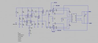
Let me share my current project, a push-pull amplifier with 807 output tubes. Since this is a rebuilt of my old construction, I wanted to reuse some parts, especially the chassis, power transformer and output transformer, at least the iron. I set some design rules for myself:
The simulation is promising, see attached circuit diagram. I will add some measuring data later.
------------------------------------------------------------------------------------------
Edit: after simulation and measuring the actual circuit it turned out that global negative feedback is unavoidable. It is because the amplifier in open loop has too high output impedance (and relatively high THD). On the other hand, with GNFB one has to take care of phase margin, so that the amplifier should be stable under complex load. I tuned it by watching the step response and experimenting with various compensation.
B+ should stay below 400V
There will be no global negative feedback
Local feedback in each stage
The output tubes will be driven from cathode followers
Perfectly symmetrical driving of the output tubes
Possibility to connect in ultralinear, triode or pentode operation
AB1 class of operation
Around 10W or more output power
Below 1% THD at full output if possible
I know the 807 shines at 600...800V anode voltage, but I wanted to build as simple as possible. Also I don't feel comfortable with that voltage level.The simulation is promising, see attached circuit diagram. I will add some measuring data later.
------------------------------------------------------------------------------------------
Edit: after simulation and measuring the actual circuit it turned out that global negative feedback is unavoidable. It is because the amplifier in open loop has too high output impedance (and relatively high THD). On the other hand, with GNFB one has to take care of phase margin, so that the amplifier should be stable under complex load. I tuned it by watching the step response and experimenting with various compensation.
Attachments
Last edited:
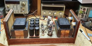
This is the old chassis that I built some 30+ years ago:
Old 807 amplifier
The electrolytic capacitors already dried out 🙁 The milliampermeters that measure the idle current were broken. So I decided on something new, something better.
Old 807 amplifier
The electrolytic capacitors already dried out 🙁 The milliampermeters that measure the idle current were broken. So I decided on something new, something better.
Attachments

Credit goes to SSassen for the cascoded LTP phase splitter idea:
Cascoded 12AX7 LTP - Stupid good performance?
and to Ite for his LTspice hierarchical ultralinear OPT model
Cascoded 12AX7 LTP - Stupid good performance?
and to Ite for his LTspice hierarchical ultralinear OPT model
I saved the current regulator diodes 1N5312 (3.9mA) and 1N5313 (4.3mA) current regulator diodes:
Microsemi - Current Regulator Diodes
They are connected parallel for 8.2mA idle current for the LTP. Also I wanted to reuse the Mills MRA-12 wirewound resistors (33k and 68k) that served well.
The bias is set with Bourns 3590S-2-103L multiturn wirewound potentiometers, also from the old chassis.
The first stage is a cascode, using E88CC tubes, my favourites due to excellent linearity. But in the new design I avoid exceeding the anode voltage limit. The driver stage were not absolutely necessary, but I wanted to drive the g1 of the output tubes from low impedance. So the effect of the Miller capacitance is reduced.
I wanted as few coupling capacitors as possible. The cascode and the cathode follower are direct coupled. There is only one coupling capacitor at the g1 of the output tube. Here I used WIMA MKS-4 (I think this is a weak point, it will be checked later).
There are reverse biased protection diodes between g1 and k of the cathode followers, not shown on the schematic. They prevent burn-out of the tubes when g1 becomes more positive than k (at turn-on and if the previous stage fails). This is mandatory for direct-coupled stages.
You might have some gain to spare, maybe look at feedback from the output tube anodes to the upper cascode grids. Needs to be cross coupled (U1 to U3 grid and U6 to U2 grid). Jhstewart9 has posted some schematics with this arrangement. You'll have to think how to get the required DC and AC levels, can be done with partially bypassed resistive divider.

In pentode mode it is 16 ohmsVery nice. What is the output impedance according to the sims in the various modes?
In UL mode (33%) it is 12 ohms
In triode mode it is 7 ohms
Perhaps the loudspeaker will be boomy at the resonance frequency
I just simulated in LTSpice. All voltages are peak values.It depends upon the speaker. How much does the cathode fb improve this?
No cathode feedback, UL=33%
Vin=0.815V
Rout=26 ohm
Vout=10V
With cathode feedback:
Vin=0.815V
Rout=12 ohm
Vout=4.75V
I measured Rout so that RL causes Vout be half of the open circuit output voltage. In this case Rout = RL.
Thank you. I once tried this with my 2A3 amp but the improvement was much more modest. As, perhaps, should be expected.
For those who want to play with the LTSpice circuit. Any ideas how could I reduce the 3rd harmonic distortion component?
I used the 6L6GC model for the 807 tubes. At least the idle current predicted by the model at -30V g1 bias is 72mA, and I measured the same on the actual circuit. The 807 and the 1625 models were not so accurate.
Any ideas on improvement welcome.
I used the 6L6GC model for the 807 tubes. At least the idle current predicted by the model at -30V g1 bias is 72mA, and I measured the same on the actual circuit. The 807 and the 1625 models were not so accurate.
Any ideas on improvement welcome.
Attachments
Your chassis looks nice! Anyway, what do these 6CG7 cathode followers in the circuit? You said you want to KISS. So, are they really necessary?
Best regards!
Best regards!
The CF helps reduce distortion in class AB2 i.e. when there is a bit of overdrive. It can deliver some grid current for the output tube, so there will be "soft clipping".Your chassis looks nice! Anyway, what do these 6CG7 cathode followers in the circuit? You said you want to KISS. So, are they really necessary?
Yes, CF's usually are used to provide grid current in class AB2 or similar applications. I see coupling capacitos, though, which prevent grid current. In case of overdrive they get charged and produce blocking distortions.
Best regards!
Best regards!
Those are big tubes ( like 6L6 ) , for just 10W is a waste  B+ should be much higher than "below 400V " .
Then you would need a good driver and eventually cathode followers
B+ should be much higher than "below 400V " .Then you would need a good driver and eventually cathode followers
- Home
- Amplifiers
- Tubes / Valves
- Push-pull 807 amplifier without global NFB