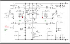
Well, those voltages will certainly help, but first I need to resolve another issue. This schematic shows R22 as 180R as opposed to 47R in your guide. Has any other value changed?
just put in pause mode until I check some things
though , values in Cook Book are official , I posted probably some intermediate file ....
ZM, that looks like the same schematic you posted above. 😛
So R22 is now 180R and I need to reach 2V88 across it. Let's see if I have that value in stock. With 47R in that position, the voltage across it only reaches 1V33.
Any other change comes to mind?
So R22 is now 180R and I need to reach 2V88 across it. Let's see if I have that value in stock. With 47R in that position, the voltage across it only reaches 1V33.
Any other change comes to mind?
Oops! It seems as if the first time around the pictured was cached. It does look different now. I'll check for those values.
Thanks!
Thanks!
no , it isn't same as one I posted by mistake in #838 *that one was earlier iteration , having two LEDs as reference for Q9 base , later changed for just one LED there)
I just edited schematic from last page in Cook Book , with green and red marked resistors
if you are seeing same schematic in posts #838 and #843 ..... something is fishy tonight- either DiyA board or our browsers
edit , I just saw you posted while I was typing
good
I just edited schematic from last page in Cook Book , with green and red marked resistors
if you are seeing same schematic in posts #838 and #843 ..... something is fishy tonight- either DiyA board or our browsers
edit , I just saw you posted while I was typing
good
Starting from the excessive, finger burning, current setting, I was able to reach 0V75 across R22. Across R24 the voltage is 1V66 and I should be able to get to 1V35 if I tweak the LED string. Do you think it is necessary? I can now keep my hand on the Pumpkin heatsink for 10 seconds, the room temperature is at 75 degrees Farenheit. In August it will reach about 85. I expected it to get hot (as you say: Papa's SUSY thingy) that's why the top of the case is made of perforated aluminum.
Here is the offset (TP1 to TP2):

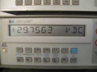
And here is TP1 to GND:

Here is the offset (TP1 to TP2):
And here is TP1 to GND:
Attachments

Starting from the excessive, finger burning, current setting, I was able to reach 0V75 across R22. Across R24 the voltage is 1V66 and I should be able to get to 1V35 if I tweak the LED string. Do you think it is necessary? I can now keep my hand on the Pumpkin heatsink for 10 seconds, the room temperature is at 75 degrees Farenheit. In August it will reach about 85. I expected it to get hot (as you say: Papa's SUSY thingy) that's why the top of the case is made of perforated aluminum.
1V66 across R24 , means 6mA , pretty close to intended 5mA , which is well in range - so leave it as is
0V75 across R22 is "just" informative value ; now - considering that info you gave me about output node offset ref. to gnd is positive , that means just one thing - lower half of preamp (Q6,Q8) is (are) lesser opened than upper half (Q5,Q7) ,so lower half having greater effective static impedance .
further , that means that current through input LTP is higher than needed , resulting in higher than needed voltage across R7 and R8 , resulting in greater than needed Ugs voltages for Q5,Q7 ; that's why we can say that upper half is too much open
now - start fiddling with WR2 , decreasing current through LTP
you'll spot right direction when offset to gnd start decreasing
and remember - that's iterative process ; as Papa sez several times - make just half of desired change , then wait (for temp. equilibrium)
one day one lazy bstrd will finally make servoed

Last edited:
Hi grimberg,
That is a beautiful build! Absolutely stunningly excellent workmanship!
Please post this in the pictures thread for your build. You have every reason to be proud of this work, and that you even built your own case kind off tops the entire DIY thing off.
So, how does it sound?
-Chris
That is a beautiful build! Absolutely stunningly excellent workmanship!
Please post this in the pictures thread for your build. You have every reason to be proud of this work, and that you even built your own case kind off tops the entire DIY thing off.
So, how does it sound?
-Chris
Thank you for the compliment. I'll gather the URLs where the photos are stored and post them in the appropriate thread.
I am still working on a noise issue and haven't had the chance to really enjoy the pre-amplifier. I'll post an update once the problem is resolved.
I am still working on a noise issue and haven't had the chance to really enjoy the pre-amplifier. I'll post an update once the problem is resolved.
Let me recap what happened, maybe you can help me find the problem.
To adjust the offset I followed the instructions in your manual and connected two voltmeters, as you described. The offset was varying very little and always stayed in the negative side. I wanted to connect it to the F4 so I did the following:
1) Adjusted WR2 until the voltage across R22 read 0V75
2) Adjusted WR1 until voltages across both R7 and R8 matched at about 5V1
I then connected one channel to one of the F4s using the XLR connector. I heard a strong buzzing sound and the music was playing, very softly and distorted, in the background.
Both my DIY F4s were played for over 100 hours driven individually and then in bridged mode using an Audible Illusions M3a tube pre-amplifier. After I disconnected the Pumpkin I re-tested the F4 using one of the XLR outputs of a Musical Fidelity M1DAC and there was no noise. This means the F4 is not at fault.
On Sunday I was busy most of the day and did not have the time to investigate further.
forget 0V75 and 5V1 as final values - those are starting/check points and values
as already explained procedure in CookBook - do not connect anything to output , ground both inputs , then you need two voltmeters - one connected between two output nodes prior to caps , second one connected between one output node and gnd
fiddling with WR2 and looking at second voltmeter you need to bring voltage from output ideally to 0V
fiddling with WR1 and looking at first voltmeter you need to bring voltage between outputs ideally to 0V
I hard-wired together the +, - and GND on the input. Measuring between TP1 (as shown in post #839) and GND, the lowest value I can get is 2V53. Between TP1 and TP2 I was able to get to a virtual 0, that is, 0.003 mVDC.
In my build I used the values specified in your manual. For R9, R10, R14, R15 and R19 I used 221R. For Q5, Q6, Q7, Q8 and Q10 I used IRF9610 and IRF610 since I already had those.
In my build I used the values specified in your manual. For R9, R10, R14, R15 and R19 I used 221R. For Q5, Q6, Q7, Q8 and Q10 I used IRF9610 and IRF610 since I already had those.
it seems you stumbled on IRF9610 with lowish Ugs for desired current
increase R22 to 120R
then try again
increase R22 to 120R
then try again
Would 150R work? I have some of those in hand.
I also have FQP3P20 that I could match and replace the IRFs. But I am not sure how that would affect the sound character of your design.
I also have FQP3P20 that I could match and replace the IRFs. But I am not sure how that would affect the sound character of your design.
sorry - I made a typo - increase R22 to 100R (not 120)
if you don't have that , decrease R7,R8 to 510R
no need to change IRF
if you don't have that , decrease R7,R8 to 510R
no need to change IRF
I increased R22 to 100R. The lowest voltage I can now get between TP1 and GND is 2V25. It changed very little.
proceed with R7,R8
if it's easier tou you , you can solder additional resistor across each of them , in value of 1K8 to 2K2
if it's easier tou you , you can solder additional resistor across each of them , in value of 1K8 to 2K2
Last edited:
One thing I would like to note is that turning WR2 from end to end only changes the offset voltage a total of 0V26. It seems as if the value of 2V25 is too far off the mark.
When you selected the IRF9510s and IRF510s for your build, in what range did you find their Vgs?
BTW, do you ever sleep? I thought vampires lived in the neighbor country.

When you selected the IRF9510s and IRF510s for your build, in what range did you find their Vgs?
BTW, do you ever sleep? I thought vampires
lived in the neighbor country.- Home
- Amplifiers
- Pass Labs
- Pumpkin Preamp - Perfect for F4