that voltage span is influenced by combo of both polarity Vgs
just do R7 and R8 ....... I'm sorta short in time now , must go
btw. sleep is for sissies
just do R7 and R8 ....... I'm sorta short in time now , must go
btw. sleep is for sissies
I soldered 2K2 resistors in parallel to both R7 and R8 on the bottom of the PCB. It changed very little as the lowest value I can now get between TP1 and GND is 2V12.
frankly , I can't remember
I'm buying them in batches of 100pcs , always asking entire plastic packages to be from same production dates
never had situation that one needs altering of these resistors , at least not in great amount
what's voltage you have across R12?
I'm buying them in batches of 100pcs , always asking entire plastic packages to be from same production dates
never had situation that one needs altering of these resistors , at least not in great amount
what's voltage you have across R12?
solder 2K7 resistor across R12 (or R26) , do the same for R17(or R28)
that will open lower side little more and hopefully allow already made changes to bring output nodes to 0 potential
that will open lower side little more and hopefully allow already made changes to bring output nodes to 0 potential
Missing pictures
Something happened to the pictures in post #829. I have uploaded them to the DIYAudio server again, and am re-posting them here.


Something happened to the pictures in post #829. I have uploaded them to the DIYAudio server again, and am re-posting them here.


Zen Mod,
After trying your recommendations in post #866 I was still unable to zero the offset. Thinking it could be a large Vgs difference between N and P channels, I purchased IRF510 and IRF9510 devices and was able to obtain closely matched pairs. I also found matched pairs of both types that had relatively close figures. The Pumpkins now have IRF510 pairs with Vgs around 3.71V and IRF9510 pairs with Vgs around 3.57V.
Unfortunately replacing the MOSFETs did not resolve the offset problem. In fact the offset measured between TP1 (as shown in post #839) and GND is now over 9V! Before soldering the new MOSFETs I installed them on the heat sink and tested for short circuits. Do you think any of the other transistors could have been damaged during testing and adjusting? What should I do next?
will think of it and re-read few pages back - tomorrow
it's 0300 now at my side , so ......... zzzzzzz
Vgs difference between N and P type never was an issue
it's 0300 now at my side , so ......... zzzzzzz
Vgs difference between N and P type never was an issue
here we go again
so , absolute offset being positive , which means lower half (current sources ) is not opened enough ...... either decrease current through LTP (do not go lower of 10-12mA (5-6mA per side) or decrease slightly source resistance of lower mosfets
which LED diodes you're using ?
what is voltage at D1 anode , ref. to gnd ?
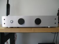
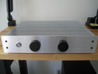
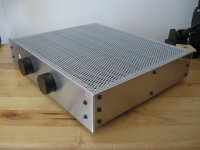
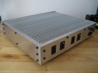
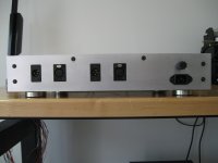
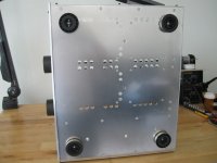
After a few years distracted by other hobbies ......
It's finally finished! Thanks for your help along the way Zen Mod.
An externally hosted image should be here but it was not working when we last tested it.
An externally hosted image should be here but it was not working when we last tested it.
It's finally finished! Thanks for your help along the way Zen Mod.
An externally hosted image should be here but it was not working when we last tested it.
An externally hosted image should be here but it was not working when we last tested it.
An externally hosted image should be here but it was not working when we last tested it.
An externally hosted image should be here but it was not working when we last tested it.
- Home
- Amplifiers
- Pass Labs
- Pumpkin Preamp - Perfect for F4