dunno - I didn't tried it that way
what I did - feed ditto in AKG Studio cans
try - nothing will go puff!
😉
what I did - feed ditto in AKG Studio cans
try - nothing will go puff!
😉
Hi all, I'm seeing something strange on my just completed Pumpy. I see DC at the input and funny behavior with clicks and pops as the volume is turned and the DC spikes to almost 2 volts. This, of course, is getting amplified about 10 times at the Pumpy output. I'm using a balanced Twisted Pair Joshua Tree stepped attenuator at the input as Zen Mod says to do. The JT does not have any DC on it when it is not connected to the Pumpy nor does the Pumpy have much DC at the input so I can't figure out where this DC is coming from. Brian at Twisted Pair suggests putting the stepped attenuator at the output against Zen Mod's advice.
did you read last page in Cook Book , about adding two pairs of resistors - for better DC stability ...... covering usage of various types of attenuators ?
however , if you still have issues with DC , after adding them , put pair of input caps , to solve that
however , if you still have issues with DC , after adding them , put pair of input caps , to solve that
Thanks ZM, I was going off an old cookbook I printed out. I'll put the resistors in and see, thanks.
I've installed the resistors and see a substantial drop in the DC but still have strange behavior while adjusting the attenuator. I've ordered some caps to try on the input. Can you help me understand what is happening. If there is no DC at the input without the attenuator why is the voltage generated when the attenuator is installed?
Thanks
Thanks
I hope you adjusted output (pre output caps) offset with attenuator on zero , which is same as you gnd both inputs
that's necessity
what's overall impedance of attenuator ?
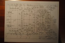
however - if you decrease red marked resistors to , say, 47K - you'll have less DC fluctuations
that's necessity
what's overall impedance of attenuator ?
however - if you decrease red marked resistors to , say, 47K - you'll have less DC fluctuations
Yes, set the offset as described to a very low level - millivolts - over a period of several hours. The Twisted Pair attenuator is a previous version but I believe they have similar specifications, this from their website;
"The kit's input impedance varies between 2.2K and 10K, with a fixed output impedance of 750R."
I know attenuator is working because I have 2 and they both behave normally in the other preamp I use.
I might try dropping the red value. I used the high 220k recommended.
Thanks for your help.
"The kit's input impedance varies between 2.2K and 10K, with a fixed output impedance of 750R."
I know attenuator is working because I have 2 and they both behave normally in the other preamp I use.
I might try dropping the red value. I used the high 220k recommended.
Thanks for your help.
What is the recommended output load for the attenuator with Pumpkin. 10k?
Just about done stuffing Shunty and Pumpkin boards. Hope to be firing them up soon.
Just about done stuffing Shunty and Pumpkin boards. Hope to be firing them up soon.
attenuator , being connected in front of  , is strictly matter of with preceding stages (sources) matching
, is strictly matter of with preceding stages (sources) matchingNewbie question. One of my sources is Pearl 2. 100k resistor at output to ground. In that case 100k, correct?
Also, would you place input selector ahead of attenuator and load each input to match source?
Also, would you place input selector ahead of attenuator and load each input to match source?
Last edited:
Newbie question. One of my sources is Pearl 2. 100k resistor at output to ground. In that case 100k, correct?
Also, would you place input selector ahead of attenuator and load each input to match source?
do not worry about trivia (Pearl's 100K -that's bleeder for output cap, nothing else )
what I was saying that value of attenuator is source(s) issue
same as with any other implementation - if you're having usual sources - use 25K attenuator
if you know that your sources are all having properly low output impedance (up to 200R) , feel free to use 10K attenuator
everything above 25K will tend to form LP filter with sissy interconnects ..... while everything under 10K will make sissy sources ....... suffer
Thanks for explaining. I have the 50k Alps Rk168 pots. Any mods needed or just get non sissy interconnects? 🙂
Also, if I wanted to use relay based attenuator such as Amb o1, how would I calculate input impendence of pumpkin?
Also, if I wanted to use relay based attenuator such as Amb o1, how would I calculate input impendence of pumpkin?
Thanks. I did not follow at first. Rred is the additional R for better DC offest stability. So R5 // Rred in parellel.
R1= 10k
R5= 100k
Rred = 150K
R5 // Rred = 60k
Input impendence = 70k
R1= 10k
R5= 100k
Rred = 150K
R5 // Rred = 60k
Input impendence = 70k
are you sure that darlingtons are genuine ?
for test , you can replace it ditto with any TO220 bjt , taking care of pinout or even N-type mosfet (G to B, D to C , S to E) ; for mosfet change R12A to 2K2
for test , you can replace it ditto with any TO220 bjt , taking care of pinout or even N-type mosfet (G to B, D to C , S to E) ; for mosfet change R12A to 2K2
Vbe of Q3a is 0.2V ?
it isn't .............. problem is that CCS can't establish it's function without load
- Home
- Amplifiers
- Pass Labs
- Pumpkin Preamp - Perfect for F4