Synopsis of Pumpkin preamp - ordered by Steen , official making thread
EDITOR'S NOTE
This thread is a subset of is a synopsis of the thread: "Pumpkin preamp - ordered by Steen , official making thread"
http://www.diyaudio.com/forums/showthread.php?s=&threadid=118994
I have removed all of the off topic posts so it is less entertaining but possibly more useful to learn about the Pumpkin
Variac
END EDITOR'S NOTE
_________________________________________________________
well ...... seems ages ago ,buried in some obscure DiyA Pass thread , after few quickie (on back of napkin) modifications of XYWZwhatever BOSOZ , my budy Lucky Luke (AKA steen) , demanded one little preamp with balls ....
few posts later , LL have some ideas about topology, perfectly good for me , just because I'm good at paper (napkin) and hand calc almost as he is good in making amps ........
little later - I already have some quickie quickie drawn , but somewhat flipped in regard to LL's idea,with added output stage(s) etc.
main reason why I flipped it is because I feel ( well - I rarely think,anyway) that's smart to use some non-audio-fancy-schmanzy Jfet , which is easy to find in near tobacco store, with all other parts .....
well - result is here (lookie lookie schmtc)
crazy process of delivery is also crazy documented in THIS
thread .........
I can just say tnx to entire OFF TOPIC MOB , just because they make my life miserable with regular questions "will it drive F4 " etc .
anyway ......... for first post is 'nuff
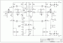
schematic:
(next post -The Shunty)...........
EDITOR'S NOTE
This thread is a subset of is a synopsis of the thread: "Pumpkin preamp - ordered by Steen , official making thread"
http://www.diyaudio.com/forums/showthread.php?s=&threadid=118994
I have removed all of the off topic posts so it is less entertaining but possibly more useful to learn about the Pumpkin
Variac
END EDITOR'S NOTE
_________________________________________________________
well ...... seems ages ago ,buried in some obscure DiyA Pass thread , after few quickie (on back of napkin) modifications of XYWZwhatever BOSOZ , my budy Lucky Luke (AKA steen) , demanded one little preamp with balls ....
few posts later , LL have some ideas about topology, perfectly good for me , just because I'm good at paper (napkin) and hand calc almost as he is good in making amps ........
little later - I already have some quickie quickie drawn , but somewhat flipped in regard to LL's idea,with added output stage(s) etc.
main reason why I flipped it is because I feel ( well - I rarely think,anyway) that's smart to use some non-audio-fancy-schmanzy Jfet , which is easy to find in near tobacco store, with all other parts .....
well - result is here (lookie lookie schmtc)
crazy process of
delivery is also crazy documented in THISthread .........
I can just say tnx to entire OFF TOPIC MOB , just because they make my life miserable with regular questions "will it drive F4 " etc .
anyway ......... for first post is 'nuff
schematic:
(next post -The Shunty)...........
Attachments
Last edited by a moderator:
setup in my livingroom... Swinging so easily 40v with 1,8 on input !!!Thank's for all the help ZenMod... Maybee it will be a while before finishing it up...
I made a
from scratch, designing my pcb (clumsy i know) myself... but the thing is playing really nice, not to mention very relaxing too. All diy'ers, which life depend's on the F4, really should consider the to drive it wild an mad...ZenMod
nice weekend...Jesper.
Attachments
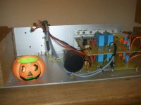
crazy danske was fast almost as his country man LL 
lykkedk earned his right to post piccies of his own because he is first who actually made non-prototype version ..........
first official pair of main boards are happily arrived at first BAF in history....... we'll hear more about Smashing and Barking tomorrow......
well- steen ordered, but he didn't count on my everlasting love for shunt regs .
as result of that love there is The Shunty ........ simply - proper reg for any eeny weeny preamp ........
my friend Oly (AKA Vangelis on DiyA) is responsible for stunning pcbs for both and Shunty ; btw. "The Shunty" is his name for that simple reg . you'll see pcb piccies in later posts.
he is also responsible for keeping me in sane boundaries ; well - almost keeping me 😉
when I drew series reg, in front of already drawn and tested shunt part of now existing Shunty, his only (and last ) comment was "that's pure demonstration of force....... why you need that ?"
I also wanna say many tnx to Off Topic Mob , which constantly make my life miserable with repetitive questions as "will it drive F4?" etc ..........
anyway - this was (is) open source project ......... my intention to make decent preamp for regular DiyA members, without braking leg and arm to find obscuremadeofpreputium audio parts (read - toshiba 3 or 7 legged fuses) ...
both schematics are here ; I intend to sell pcbs along with matched crucial parts , in several levels ........ just main boards with parts, just Shunty with few important parts (if they exist at all) , complete package, main boards with just one Shunty ( if you are bean counter) etc.
to cut a story..........
here is The Shunty schematic:
lykkedk earned his right to post piccies of his own
because he is first who actually made non-prototype version .......... first official pair of main
boards are happily arrived at first BAF in history....... we'll hear more about Smashing and Barking tomorrow......well- steen ordered
, but he didn't count on my everlasting love for shunt regs . as result of that love there is The Shunty ........ simply - proper reg for any eeny weeny preamp ........
my friend Oly (AKA Vangelis on DiyA) is responsible for stunning pcbs for both
and Shunty ; btw. "The Shunty" is his name for that simple reg . you'll see pcb piccies in later posts.he is also responsible for keeping me in sane boundaries ; well - almost keeping me 😉
when I drew series reg, in front of already drawn and tested shunt part of now existing Shunty, his only (and last ) comment was "that's pure demonstration of force....... why you need that ?"
I also wanna say many tnx to Off Topic Mob , which constantly make my life miserable with repetitive questions as "will it drive F4?" etc ..........
anyway - this was (is) open source project ......... my intention to make decent preamp for regular DiyA members, without braking leg and arm to find obscuremadeofpreputium audio parts (read - toshiba 3 or 7 legged fuses) ...
both schematics are here ; I intend to sell pcbs along with matched crucial parts , in several levels ........ just main boards with parts, just Shunty with few important parts (if they exist at all) , complete package, main boards with just one Shunty ( if you are bean counter) etc.
to cut a story..........
here is The Shunty schematic:
Attachments

John,
The Pumpkin is the actual pre-amp
Shunty is the regulated power supply for the Pumpkin pre.
Hope that helps.
Ryan
The Pumpkin is the actual pre-amp
Shunty is the regulated power supply for the Pumpkin pre.
Hope that helps.
Ryan
mpmarino said:Page 3 is most informative.
agree ...........
you can't so easy find schematic of INT-150 ........
Hi ...
ZenMod, when you tell to place voltmeter, at outerpin of C4 / C5, you mean at the point, where R13 meets C4(-out) , and where R18 meets C5 (+out) right ? - seem's a little hard to understand 100% (at least for me 😉). Well my pumpkin have been playing for several week now., but i will recheck the adjustment's when i somehow in future get chance to put it in box 🙂
C4 / C5 is the 10uF outputcap's you're meaning in the assembly-instruction's right ???
Jesper.
lykkedk said:Hi ...
ZenMod, when you tell to place voltmeter, at outerpin of C4 / C5, you mean at the point, where R13 meets C4(-out) , and where R18 meets C5 (+out) right ? - seem's a little hard to understand 100% (at least for me 😉). Well my pumpkin have been playing for several week now., but i will recheck the adjustment's when i somehow in future get chance to put it in box 🙂
C4 / C5 is the 10uF outputcap's you're meaning in the assembly-instruction's right ???
Jesper.
let me see ........
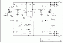
C4 and C5 from Pumpkin schematics ;
outer pins - physically outer on pcb , far left and far right side ......
I'm clearer now?
😀
C4 and C5 from Pumpkin schematics ;
outer pins - physically outer on pcb , far left and far right side ......
Yes Yes 😀 I know, i thought it over today, and see what you mean, regarding the placement of the output cap's...
I have attached a schematic, with 3 grey spots on, pointing on the meassuring point's, are they located the right places on schm. ???
Jesper.
Attachments
lykkedk said:
Yes Yes 😀 I know, i thought it over today, and see what you mean, regarding the placement of the output cap's...
I have attached a schematic, with 3 grey spots on, pointing on the meassuring point's, are they located the right places on schm. ???
Jesper.
grey spots are on spot 😉
Good ZenMod.... Then things will work for dummies (ahh like me ???) 😀 too !!!
Btw... I use a 10k stereo alps pot on input, you somewhere in the past mentioned something about what's fit your'e source best... Well i donno what impedance my DDDAC / PearlPhono have, so do you have any good suggestion, for an allround pot... meaning values both for stereo + eventually an balanced one. Maybee this could interest someone else too 😀 ... Anyway, keep up good work ...
Damn... i haven't got much time listning to dreky... and finishing up thing's - Right now i am designing an inputselector, with 3 unbal RCA input's + 1 balanced input + balanced/unbalanced switch for output, for futureproof - all along with a switch, where you can switch between two toslink input's... All that must go into dreky too.
I was inspired to make this myself, looking at twistedpears darwin-input-selector btw:.. But this is way O.T. sry for that.
Jesper.
Btw... I use a 10k stereo alps pot on input, you somewhere in the past mentioned something about what's fit your'e source best... Well i donno what impedance my DDDAC / PearlPhono have, so do you have any good suggestion, for an allround pot... meaning values both for stereo + eventually an balanced one. Maybee this could interest someone else too 😀 ... Anyway, keep up good work ...
Damn... i haven't got much time listning to dreky... and finishing up thing's - Right now i am designing an inputselector, with 3 unbal RCA input's + 1 balanced input + balanced/unbalanced switch for output, for futureproof - all along with a switch, where you can switch between two toslink input's... All that must go into dreky
too.I was inspired to make this myself, looking at twistedpears darwin-input-selector btw:.. But this is way O.T. sry for that.
Jesper.
lykkedk said:Good ZenMod.... Then things will work for dummies (ahh like me ???) 😀 too !!!
Btw... I use a 10k stereo alps pot on input, you somewhere in the past mentioned something about what's fit your'e source best... Well i donno what impedance my DDDAC / PearlPhono have, so do you have any good suggestion, for an allround pot... meaning values both for stereo + eventually an balanced one. Maybee this could interest someone else too 😀 ... Anyway, keep up good work ...
well - did you saw AR2's solution - two Black Widows (AKA Blue Velvets 😉 ) , each stereo 50K pot ?
one per channel, so you have in same time balance too ....
that variant is both marked as good and also as bad , depending which personal preference is in question.....
anyway - 4 channel ALPS aren't so expensive - I think somewhere in range of 40 Euro ............... look HERE ..... that's my friend from Geek toob forum ......
I presume that you don't want Magura San to make eeeny weeeny attenuator for you , except if you have spare room just for them
in any case - it's better to use as low attenuator value as you can, considering output impedances of your sources ; if sources are happy with 10K pot - then use 10K pot ; anyway Pumpkin is made with input impedance in that range ( remember value of resistors in both J310's gates )
Damn... i haven't got much time listning to dreky... and finishing up thing's - Right now i am designing an inputselector, with 3 unbal RCA input's + 1 balanced input + balanced/unbalanced switch for output, for futureproof - all along with a switch, where you can switch between two toslink input's... All that must go into dreky
I was inspired to make this myself, looking at twistedpears darwin-input-selector btw:.. But this is way O.T. sry for that.
Jesper.
my advice , and you know that I'm always willing for at least one
is - use 4 channel volume pot , use only XLR connectors on input and also on output , use mini relays for input selector ( one double Takamisawa per channel input , so - when rely is not in use , both signal rails are grounded .then - if you need to use nonbalanced source, just short gnd and minus leg ditto in cable XLR of that source
clear enough ?
I'm not sure ........ sometimes is hard to force my Engrish to follow what I want
clear enough ?
yeah, I think so... Your Engrish is better than you think 🙂
Ya know... I've been toying with the idea of building a separate input select/attenuator module with remote volume. Sort of what someone might build as a passive 'pre amp'( I always wondered how you could have a passive preamp?) Fully balanced input to output using whatever good components I have in the drawer. This would simply go between the sources and the pre. The actual pre would just be a box with 1 in and 1 out. Nice n' easy.
Why? you ask?
Maybe you didn't ask why- but I'll tell you anyway. Whenever I build a preamp circuit I'm finding that the most difficult part is the in selector and the attenuator - partswise. Also, it's hard to compare circuits because I never end up with the same type of attenuator. In doing this I would never have to scrape for an attenuator or input selector again - just keep using the same one.
Whadya think?
mpmarino said:
..................
Ya know... I've been toying with the idea of building a separate input select/attenuator module with remote volume..................
Whadya think?
"....cunning plan......"
( Babelfish 2SJ74 are matched and packed ; post office tomorrow ....today........ now is 05:27 local time 😉 )
- Status
- Not open for further replies.
- Home
- Amplifiers
- Pass Labs
- Pumpkin preamp - More Boring Making Thread