- Twiddle thumbs until everything comes in, I'll probably use Seeed Studio or dirtypcbs for the PCBs, so it'll take a few days to fab and a week or two to arrive.
Please go for Elecrow, NOT for dirtypcbs - their boards are really low-q.
Elecrow lastly updated/changes their fab/manufacturer and are from excellent quality.
--------------
And please put a warning into silkscreen to not run the board without load.
...and looking at dug pics I think it isn't just me, it seems several pics show ampboard-gnd connected to negative input, for your ampboards it just is visable easily🙂
INR/L- (negative input) is coupled to GND via a capacitor, not straight down, because the inputs are biased.
So you wont connect your signal-GND straigt to the negative inputs in no way.
INR/L- (negative input) is coupled to GND via a capacitor, not straight down, because the inputs are biased.
So you wont connect your signal-GND straigt to the negative inputs in no way.
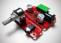
Is c35 connected to gnd or is it connected to input terminal?
I've ordered easily a dozen different things now between Seeed and DirtyPCB (whom I suspect use the same fab) without any major issues, occasionally you get a board with a misaligned silkscreen/solder mask but considering the price, you're still well ahead even if you discard some boards. I'm planning on ordering way more PCBs than I actually need and doing my own inspection, discarding any boards with obvious silkscreen/soldermask alignment.Please go for Elecrow, NOT for dirtypcbs - their boards are really low-q.
Elecrow lastly updated/changes their fab/manufacturer and are from excellent quality.
--------------
And please put a warning into silkscreen to not run the board without load.
They do 100% e-test and I'm not pushing the limits of their process at all, their limits are 5 mil trace/space, my minimum trace is 10 mil and my minimum space is 13. Their minimum drill is 12 mil, my minimum is 16 (under TPA only) and 20 elsewhere.
I'll add the 'don't run unloaded' text to the PCB, if I can find room to fit it 🙂 thanks.
Holy living expletive, 4 layer PCBs are dirt cheap at elecrow.
Even though it's electrically unnecessary with this design, part of me is tempted to do it here, primarily for thermal reasons...
Even though it's electrically unnecessary with this design, part of me is tempted to do it here, primarily for thermal reasons...
INR/L- (negative input) is coupled to GND via a capacitor, not straight down, because the inputs are biased.
So you wont connect your signal-GND straigt to the negative inputs in no way.
huh , your advise is too couple the most noise from the dirty amp ground plane into the differential input.'
Do this instead > use twisted pair from MP3 player floating into analog + to - inputs (with DC blocks of coarse). avoid any input connections to the dirty grounds. > incudes larger values of DC blocking caps.
DO NOT connect coax shields to the amps in any way!!
in-fact if you were smart would use ferrite CM baluns on every input / output to these noisy things
Last edited:
Yes that seems how Dugs and this future ampboards are, no negative input to ampgnd but to source gnd, it should have best noise performance according to many datasheets, however not so here, not with any source or connecting wires, with transformers to inputs the same added noise is there. And pictures in dug gb thread show other people connect ampboard gnd to negative input too, dug terminal is + and - input and gnd, gnd terminal is ampgnd. So I am guessing more people have same added noise when negative input isn't to ampgnd. It occurs with all pbtl 3116 ampboards I have here, not just dugs have added noise, none of the stereo btl chinese amps have option, they connect negative through cap to ampgnd near chip all the time, they do not have the added noise option.
Holy living expletive, 4 layer PCBs are dirt cheap at elecrow.
Even though it's electrically unnecessary with this design, part of me is tempted to do it here, primarily for thermal reasons...
Ja, 6/6mil 2 Layer 0.8mm from Elecrow..
Attachments
R36/37/42/43 do put a 30K (single ended) / 60K (differential) load on the output of your pot, which will mess with the taper slightly. If you use a 10K pot it won't make much of a difference, 5K will be even better.I know datasheet tells me to put gnd for negative SE inputs at source, but that always seems to increase noise here, so I connect negative to ampboard gnd. Would r37 and r43 reduce/prevent that noise? (btw same added noise here with inputtransformers)
Do these 4 resistors affect inputimpedance and attenuation, I mostly use passive log pots, do they look like the loglaw resistors too added to linear pots? I don't remember clearly.
Of course you could always just haul the resistors off the PCB if their presence offends you 🙂
huh , your advise is too couple the most noise from the dirty amp ground plane into the differential input.'
Do this instead > use twisted pair from MP3 player floating into analog + to - inputs (with DC blocks of coarse). avoid any input connections to the dirty grounds. > incudes larger values of DC blocking caps.
DO NOT connect coax shields to the amps in any way!!
in-fact if you were smart would use ferrite CM baluns on every input / output to these noisy things
Well, that's not the S.E. approach but differential. I never had any issues doing so with S.E.. (I.e. noise)
I really can't understand why everyone's running into noise problems now and then.
But will look into this.
Edit:
http://www.ni.com/white-paper/3394/en/
Table 1 left/middle shows your config. (Floating source..)
Last edited:
Ja, 6/6mil 2 Layer 0.8mm from Elecrow..
0.150/0.150 most SMD is hard metric these days (apart from ancient SOICs) go METRIC😉
Balanced routing can be edge coupled (both traces on same side of board) or broadside coupled (signals on two adjacent layers) good for sensitive analogue as well.
I really can't understand why everyone's running into noise problems now and then.
I can, it's my specialty cleaning up other folks mistakes on complex RF/analog <> digital systems. modems radios
Im working on some PV MPPT SMPS stuff right now. trying to make it bullet proof I/O goofs etc
Last edited:
R36/37/42/43 do put a 30K (single ended) / 60K (differential) load on the output of your pot, which will mess with the taper slightly. If you use a 10K pot it won't make much of a difference, 5K will be even better.
Of course you could always just haul the resistors off the PCB if their presence offends you 🙂
infact linear taper pots can be made to approximate log taper ( audio pots ) by loading them on the wiper. so it's a good thing (done on clean grounds hehe )IMO
see Fig 8 http://sound.westhost.com/pots.htm
Last edited:
I can, it's my specialty cleaning up other folks mistakes on complex RF/analog <> digital systems. modems radios
Im working on some PV MPPT SMPS stuff right now. trying to make it bullet proof I/O goofs etc
Alright then. 😉
Well, that's not the S.E. approach but differential. I never had any issues doing so with S.E.. (I.e. noise)
I really can't understand why everyone's running into noise problems now and then.
But will look into this.
Edit:
Ground Loops and Returns - National Instruments
Table 1 left/middle shows your config. (Floating source..)
The problem with that link > do not confuse class D amp gnd as a measurement ground. take the reference at the clean ground.
for EMI that is a dedicated earth ground connected to a bench ground plane. this is the measurement ground zero> spectrum analyzer (radio) input is at this reference.
A simple solution for class D > is the player has no ground its completely floating with its own batteries. BUT as soon as you include class D in a common system with shared supplies and grounds you must use true differential interfaces. look up common mode noise and measurement errors.
Last edited:
infact linear taper pots can be made to approximate log taper ( audio pots ) by loading them on the wiper. so it's a good thing (done on clean grounds hehe )IMO
see Fig 8 Potentiometers (Beginners' Guide to Pots)
In a conventional pot (whatever law) the worst piece of resistance is the wiper-track interface. Therefore you want as little current as possible through this resistance, so any resistance variation does as little damage as possible. Adding a law-changing resistor to a linear pot does the very opposite. OK in an emergency if the right pot is not available, but I would avoid it when possible.
There are some other posts referencing to this popular method mentioning increased distortion, but nobody can stop people saying they think it is best or a good thing. They stop saying that after posts like the above in these other threads so I guess the people saying it isn't advisable are correct here, it is a bad thing. I don't want bad 😉
yes avoid high currents on pots. that's the job of its application not a general do n don'ts check list.
use high input impedances, use low source impedance, and by all means avoid DC current on signal lines.
a wiper shunt resistance is not bad, if it is a problem you're probably using it in the wrong application> on inverting inputs is a common mistake.
use high input impedances, use low source impedance, and by all means avoid DC current on signal lines.
a wiper shunt resistance is not bad, if it is a problem you're probably using it in the wrong application> on inverting inputs is a common mistake.
Last edited:
Yeah, don't run significant current through a pot/trimmer wiper if you can. The contact area between the wiper and the track can be very small, causing localized heating/oxidization/etc at the interface.
We had a bad case of this in a power supply design at a previous job, where a trimmer was configured as a rheostat in the feedback loop of a power supply with current continuously going through the wiper. Over time the power supply output would drop due to the wiper resistance going up. Wiggling the pot back and forth would temporarily restore it, but you'd eventually end up with a 'dead spot' in the pot and you'd have to either set it high or low, or change the pot. Ultimate fix was changing the damn feedback resistors to 1% ones, using a higher grade TL431, and getting rid of the pot.
We had a bad case of this in a power supply design at a previous job, where a trimmer was configured as a rheostat in the feedback loop of a power supply with current continuously going through the wiper. Over time the power supply output would drop due to the wiper resistance going up. Wiggling the pot back and forth would temporarily restore it, but you'd eventually end up with a 'dead spot' in the pot and you'd have to either set it high or low, or change the pot. Ultimate fix was changing the damn feedback resistors to 1% ones, using a higher grade TL431, and getting rid of the pot.
Holy living expletive, 4 layer PCBs are dirt cheap at elecrow.
Even though it's electrically unnecessary with this design, part of me is tempted to do it here, primarily for thermal reasons...
I was going to do my TPA3116 design in 2-layer. Although I was planning to use a TPA3116 with the power pad on the top of the pkg with a HS.
I did my portable media player in a 4-layer from Imagineering, 2 of 30 sq in pcbs for $100, which was the new customer deal. I had too, it was way to dense for a 2-layer. 4 layers allows you to have a dedicated supply and ground layer, so it does make things so much easier and has other advatages.
The boards from Imagineering were excellent. I used a 16 mil fhs for the vias and 8/8mil line/space.
If you chose 4-layer, I won't complain about the modest cost increase!
- Status
- Not open for further replies.
- Home
- Amplifiers
- Class D
- "Proper" TDA3116 PCB