I did my headphone DAC design from several years back in 4 layers, using the 'no touch' service from Sierra Proto Express. 160x100cm "no touch" service, cost me $122 USD plus probably $60-70 in fedex/duties/taxes and other crap to get it here.
I've also done countless 2-layer protos using Alberta Printed Circuits, usually leaving off the soldermask and dealing with traces going missing during rework, but still paying $60-70 for two boards. Ugh. Gotta say, I absolutely love this cheap chinese PCB manufacturing that's popped up, it's greatly increased my electronics output. Must hurt for manufacturers on this side of the pond though.
Went over the numbers for this one, 1/2oz copper inside won't greatly help the thermals, and I don't think the power supply impedance up in the >100MHz band where the PCB starts to make a difference really matters. I'm also not bringing a digital supply rail to a bunch of different chips so it won't help routing. Pretty much the only reason to do it would be bragging rights. I'll keep it 2 layer.
I agree, these el' cheapo asian pcb mfg's make things a lot more practical for us small guys to do small batch proto's. I will never have to etch another pcb again 🙂
Also agree to not design to their mfg limits, easing off on the design rules, should make it easier for them to mfg and have less defects.
Good idea to stick with a 2-layer pcb for this design.
I actually found a few old TI LM339N in my parts bin, just for the fun of it I'll get my BIM board out and play with it, real life testing instead of a sim 🙂
I'm using a LM393, not a LM339, but they should be close enough. Going by the schematic on page 1 of this guy:
http://www.ti.com/lit/ds/symlink/lm393-n.pdf
If you tie +IN to V+ and -IN to ground... Q1 will be off (no Vbe), so Q2 will be off, and no current will flow into the emitter of Q5, and Q5/Q6 will both be off. This means 100uA will flow into Q7, shunting base current from Q8 and turning it off, so the output will be open. With -IN at V+ and +IN at ground... Q3/Q4 will be off, Q1/Q2 will be on. 100uA will flow through Q2 into Q5 as well as the base of Q6, turning on Q6 and shunting Q7's base so Q7 will be off. This leaves Q8 driven by the rightmost 100uA current source, so it will be on.
LM339 has the same schematic, just with the Q numbers missing and different current sources, page 3:
http://www.ti.com/lit/ds/symlink/lm339.pdf
But definitely do the bench test 🙂
Last edited:
R36/37/42/43 do put a 30K (single ended) / 60K (differential) load on the output of your pot, which will mess with the taper slightly. If you use a 10K pot it won't make much of a difference, 5K will be even better.
Of course you could always just haul the resistors off the PCB if their presence offends you 🙂
Well you could give your answer more clarity by just saying: for best result use 5k pot with this proper3116/8 🙂
(It is completely different from the 50k pot advise in big thread and wiki, were it also is mentioned 100k pot will work just fine too, "just fine too" is comparable with your "not much of a difference" I suppose)
Irribeo, the best would be 0R, because thats what TI supposed when they'd written the datasheet. The pop-problem comes from the RC-time-constant, formed by the coupling-C and the output-impedance of the player.
You could even go for a 1k-pot, so maximum impedance seen from source side would be 500R, but this will seriously load the players output-stage, where modern CD-Players can drive a minimum load of 1-2k.
...
I.E.:
So having 2u2 and a 5k pot: 2u2*2k5= 5.5ms...
You could even go for a 1k-pot, so maximum impedance seen from source side would be 500R, but this will seriously load the players output-stage, where modern CD-Players can drive a minimum load of 1-2k.
...
Also, take care to match the impedance seen at the positive and negative inputs
to avoid nuisance DC detect faults.
TI datasheet , 7.3.7: "input impedance should be <1ms to avoid plopp"
I.E.:
So having 2u2 and a 5k pot: 2u2*2k5= 5.5ms...
Last edited:
I'd rather explain why, so people can learn how this stuff works, than give out numbers without any explanation.Well you could give your answer more clarity by just saying: for best result use 5k pot with this proper3116/8 🙂
(It is completely different from the 50k pot advise in big thread and wiki, were it also is mentioned 100k pot will work just fine too, "just fine too" is comparable with your "not much of a difference" I suppose)
At high frequency, the impedance seen by the volume pot will be loaded by the 30K of this circuit board, in parallel with the input resistance of the TPA which varies with gain setting.
Latest. Only difference is the PLIMIT pot addition, and reordering of the SW2 DIP switch so I could cram the pot/resistor/cap in there.

And ZofZpcb is a pretty awesome gerber viewer:

And ZofZpcb is a pretty awesome gerber viewer:
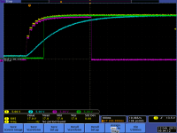
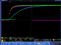
Done, see attached, 2 traces of a power up cycle, showing some glitching. I only had a 20V supply, used 100K r's in place of the 150K & a 27K for R19 = close enough for this test.But definitely do the bench test
1) yel: D1/C33
2) blu: R25/C30
3) purple: mute
4) grn: sdz
For the power down cycle, I am thinking that R19 should be connected to the anode side of D1 instead of the cathode side which is being held up by the charge on C33?
I will make the change a capture another trace with this setup change.
Does ZofZpcb read in the Excellon drill data too? like gerbTool does
Attachments
Last edited:
And ZofZpcb is a pretty awesome gerber viewer:
[/QUOTE]
Looks like Elecrow Black HASL. 😀 (by doctormord) 😀
Edit:
I would lastly consider to have the mounting holes not plated. Thats why you have the restring with plated vias.
Looks like Elecrow Black HASL. 😀 (by doctormord) 😀
Edit:
I would lastly consider to have the mounting holes not plated. Thats why you have the restring with plated vias.
Last edited:
Done, see attached, 2 traces of a power up cycle, showing some glitching. I only had a 20V supply, used 100K r's in place of the 150K & a 27K for R19 = close enough for this test.
1) yel: D1/C33
2) blu: R25/C30
3) purple: mute
4) grn: sdz
For the power down cycle, I am thinking that R19 should be connected to the anode side of D1 instead of the cathode side which is being held up by the charge on C33?
I will make the change a capture another trace with this setup change.
Power-down is not covered in this configuration. Btw. Did you limited VCC risetime?
1/4 of potvalue often used as max out impedance seen by ampboard, but probably assuming source outputimpedance is near zero? You assume source output impedance is 1/4 potvalue too?Irribeo, the best would be 0R, because thats what TI supposed when they'd written the datasheet. The pop-problem comes from the RC-time-constant, formed by the coupling-C and the output-impedance of the player.
You could even go for a 1k-pot, so maximum impedance seen from source side would be 500R, but this will seriously load the players output-stage, where modern CD-Players can drive a minimum load of 1-2k.
...
I.E.:
So having 2u2 and a 5k pot: 2u2*2k5= 5.5ms...
Input impedance potvalue seen by source often assumed potvalue if ampboard/load impedance is high enough, here you also halve the value, so I assume inputimpedance ampboard isn't high enough to take just potvalue looking from source?
Don't know what my cd can stable drive, wireless dac for pcaudio probably has bigger problems.
In other threads, I kept missing the "buy" opportunity within the tech discussions... so this time, I'll mention in advance that I would be interested in one fully built card.
Thanks
Ron
Thanks
Ron
So after messing around with adding hysteresis to the comparator circuit and realizing I'm quickly running out of board space and making a very inelegant circuit... I think I'm gonna go back to the microcontroller approach.
I'll probably use an ATTiny13A, assuming it has enough pins for what I've got in mind. It's fairly cheap, and it comes in a SOIC which means it's easy to program in a socket and toss in a bag along with a bare PCB.
And thinking about the input impedance/input coupling cap potentially causing a power-on pop, I'll hang a second trimmer off the uC which sets the power-on unmute delay. So if you use gigantic coupling caps and/or a high impedance source, you can dial it up to a second or more.
Operation will be pretty dumb. Start up, measure power supply until it's deemed stable, measure delay pot, wait delay #1, raise SDZ, wait delay #2, lower MUTE. With extra stuff jammed in there for FAULTZ handling, power loss detection, etc.
No, this is just the way my home made power supply starts up. It is a LM317 based design, for that output, which is variable.Did you limited VCC risetime?
It makes no difference!!I am thinking that R19 should be connected to the anode side of D1 instead of the cathode side which is being held up by the charge on C33?
In my TPA3100D2 design, I did not do anything special for a power-down cycle, the TPA3100D2 behaves well, with no annoying power down noise coming out from the speakers. Unlike a class "AB" type of design, which usually needs an "AC" fail detector to isolate the load as the supplies collapse.
BTW, that is exactly what I did with the TPA3100D2 design, use the MCU, a xmega in my case, to control the mute and sdz. Tiny avr's are great for this application. Now you need a voltage regulator for it too!
What language(s) do you use for Atmel AVR? I have been using BASCOM-AVR for a while now, it is a fine compiler, with great support from Mark Alberts the creator.
Last edited:
I use AVR-GCC (built into the current Atmel Studio tools) and write everything in C, occasionally using assembly code for weird tasks. Regulator isn't an issue, 78L05 is dirt cheap and stable with 0.1uF on the output (I'll use a 220n bootstrap cap).BTW, that is exactly what I did with the TPA3100D2 design, use the MCU, a xmega in my case, to control the mute and sdz. Tiny avr's are great for this application. Now you need a voltage regulator for it too!
What language(s) do you use for Atmel AVR? I have been using BASCOM-AVR for a while now, it is a fine compiler, with great support from Mark Alberts the creator.
Tiny13A fits and has enough pins. Excuse the huge picture.

edit: I'll probably yank the 30K pullups on MUTE and FAULTZ. Means these pins are undefined with the device in reset, but setting the RSTDISBL fuse and using it as an I/O pin to read the standby input fixes that 😉 Part can still be HVSP reprogrammed in-circuit if need be.
Last edited:
Sounds good, thanks for your interest!In other threads, I kept missing the "buy" opportunity within the tech discussions... so this time, I'll mention in advance that I would be interested in one fully built card.
Thanks
Ron
I'll cram the microcontroller onto the card tonight in place of the comparator, finish BOM, come up with final pricing and probably kick off the group buy on the weekend.
I'll take orders for ~2 weeks, then order PCBs, ordering about twice as many as I need. Then I'll wait about a week (taking orders during this time), shut down the group buy and make the Digikey/Mouser orders.
Tiny13A fits and has enough pins.
Good stuff.
Pretty much exactly what I did. I do not see any issues.
I did not even use a ADC, to monitor the supply, but it is a good feature. I could display the operating voltage, just another feature 🙂 next rev or model !!
The portable runs off USB power too (only headphones, no TPA) , I just sensed the input supply (level shifted), on a I/O and shutdown with a level change & triggered an interrupt routine to shutdown the TPA3100. It worked great.
Suggest to make it a two step approach, get a quick proto running while you are taking orders.
You can get your test fixture up and going at that time too. I guess you can program the ATtiny in circuit, ISP pins TP access.
I remember building these fixtures at Motorola, no mcu's to use at that time, only masked 3870's to work with. Most fixtures built using state machines running 4000 CMOS logic, all hand wired. Push button -> pass/fail 🙂
One smart EE had the order processing conveyor system running using this method, what a mess of logic = nuts. Hand drawn on a "D" size page. Kept the traffic down on the assembly floor 🙂 More production!!
We were lucky, supply the machine shop with the pcb, pogo pins, chassis and TP locations, they returned with a milled nylon fixture mounted on a Hammond chassis 🙂 I assume you are the machinist too?
Lets hope (use best efforts) that it is a flawless first rev BUT there is always the unknown. Have you previously used all the library components?, reviewed them all? I have never, or refuse to use, the default libraries that come with the CAD packages. It just a word of caution from my experiences. Many libraries do not understand DFM issues.
If you want to shoot me a couple of pcb's, I can solder one up and test it out. I have a programmer (AVRISP mkII) which I use all the time.
Your call, your show 🙂
Last edited:
I use AVR-GCC (built into the current Atmel Studio tools) and write everything in C, occasionally using assembly code for weird tasks. Regulator isn't an issue, 78L05 is dirt cheap and stable with 0.1uF on the output (I'll use a 220n bootstrap cap).
Tiny13A fits and has enough pins. Excuse the huge picture.
edit: I'll probably yank the 30K pullups on MUTE and FAULTZ. Means these pins are undefined with the device in reset, but setting the RSTDISBL fuse and using it as an I/O pin to read the standby input fixes that 😉 Part can still be HVSP reprogrammed in-circuit if need be.
Well, thats look quite similar to our approach.

Except we use Z-Diode for 78L05. You can put FAULTZ on the voltage sense pin as well. It then is pulled above the threshold by that voltage divider, so you dont need to use the /RESET pin. 😉
Edit: I like that /RESET approach, but with the normal operation (as a reset), The pullups/downs holds the amp in standby then.
Last edited:
In other threads, I kept missing the "buy" opportunity within the tech discussions... so this time, I'll mention in advance that I would be interested in one fully built card.
Thanks
Ron
No doubt. Add me to the list of possibly interested buyers.
I contemplated using a zener regulator but the Tiny13 can pull several mA during programming, I'd be dumping a quarter watt in the series resistor to maintain regulation unless I supply external programming current. 78L05 seemed a bit more suitable.Well, thats look quite similar to our approach.
Except we use Z-Diode for 78L05. You can put FAULTZ on the voltage sense pin as well. It then is pulled above the threshold by that voltage divider, so you dont need to use the /RESET pin. 😉
Edit: I like that /RESET approach, but with the normal operation (as a reset), The pullups/downs holds the amp in standby then.
Gonna keep with the reset approach I think. Creating the 78L05 part now, I'll have a layout/schematic to post in a short while.
- Status
- Not open for further replies.
- Home
- Amplifiers
- Class D
- "Proper" TDA3116 PCB