This is a new thread started from a rando post here: https://www.diyaudio.com/community/threads/headshakes-far-field-3way.382393/post-7434715
I've made a 3" ETON + t25b box before and this will be a reworking of the same setup. I like the idea of being able to swap out the HF/MF boxes.
The Seas L26ROY is in a PartsExpress box. It is by chance that it fits without any adjustment.
I will measure the drivers next and make an ideal sim to reference along the way.
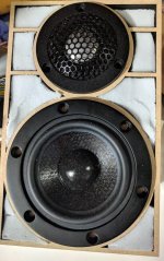
The JA-0801 is in a foam baffle for now. I used some Loctite power grab and some wood skewers to hold the stand together. Metal screws are holding the driver down.

The hypex FA123 can be seen at the bottom of the image.
The tweeter will be picked later.
A translated info sheet about the dome:

I've made a 3" ETON + t25b box before and this will be a reworking of the same setup. I like the idea of being able to swap out the HF/MF boxes.
The Seas L26ROY is in a PartsExpress box. It is by chance that it fits without any adjustment.
I will measure the drivers next and make an ideal sim to reference along the way.
The JA-0801 is in a foam baffle for now. I used some Loctite power grab and some wood skewers to hold the stand together. Metal screws are holding the driver down.
The hypex FA123 can be seen at the bottom of the image.
The tweeter will be picked later.
A translated info sheet about the dome:
I have some eq to roll off the ja-0801. No boosts or other eq yet but it looks pretty flat.
The measurements are at 1m but the mic stand slipped so this is slighly lower than on-axis. My darn stand needs to be crazy tight or it slips down after a few min.
I was curious about the baffle size and messing with the decay. VCAD predicted some mess around 2k.
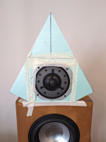
The tri baffle is just some shapes stuck onto the square baffle. The goal was to see if the GD and decay would change.
Square vs Triangular
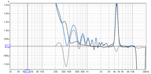
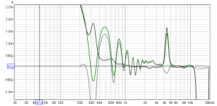

My very rough estimate of the sd and baffle sim. The tri baffle is the orange line:
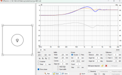
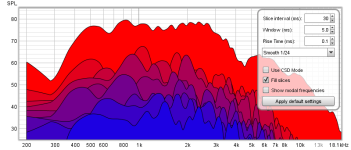
My aim is for a very random decay and smooth GD. If the baffle is mostly square 21cm shape then that shows up in the decay:
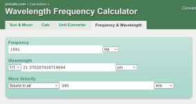
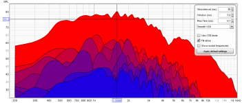
This is just a repeat of the square baffle with a curser to show the WL of the baffle.
Some better on-axis measurements are next but maybe I want a baffle with a nice random shape but not larger than a 1khz WL?
The measurements are at 1m but the mic stand slipped so this is slighly lower than on-axis. My darn stand needs to be crazy tight or it slips down after a few min.
I was curious about the baffle size and messing with the decay. VCAD predicted some mess around 2k.

The tri baffle is just some shapes stuck onto the square baffle. The goal was to see if the GD and decay would change.
Square vs Triangular


My very rough estimate of the sd and baffle sim. The tri baffle is the orange line:

My aim is for a very random decay and smooth GD. If the baffle is mostly square 21cm shape then that shows up in the decay:


This is just a repeat of the square baffle with a curser to show the WL of the baffle.
Some better on-axis measurements are next but maybe I want a baffle with a nice random shape but not larger than a 1khz WL?
Right, look to room ratios for shapes pg. 242. As for the 1 kHz, not sure of your performance goal, but with 'freehand' shapes an averaged frequency is normally required/desired.
Thanks, @GM . Cool book link. I read the section you pointed to- it seems to be more about LF and rooms. I will read through the whole thing.
I am just messing arround ATM. The baffle is in the response, so my goal is to have a shape that helps and not hurts. I tend to focus more on the baffle shape and do not really think about the room. A rounded and asymmetrical shape is probably more ideal but I like to compare things if it is easy enough.
I am just messing arround ATM. The baffle is in the response, so my goal is to have a shape that helps and not hurts. I tend to focus more on the baffle shape and do not really think about the room. A rounded and asymmetrical shape is probably more ideal but I like to compare things if it is easy enough.
The room ratio plot shape reminds me of:
https://www.smithsonianmag.com/smar...-with-a-pattern-that-never-repeats-180981899/
An non-repeating shape.
I'll give it a go. Thanks again!

https://www.smithsonianmag.com/smar...-with-a-pattern-that-never-repeats-180981899/
An non-repeating shape.
I'll give it a go. Thanks again!

Did some cutting and will compare a square, triangular, room ratio, and chiral aperiodic shapes. It might just work out that the smallest baffle is best but this will be neat to see.
Paper on aperiodic:
https://arxiv.org/abs/2305.17743
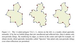
Nothing is perfect so I thought I'd just cram 3 sides into the room ratio and chiral aperiodic shapes.
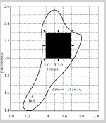
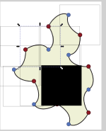
I did an ok job trying to freehand it with some gridlines.
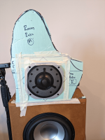
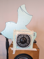
Measurements are next up. The baffle is not mounted flush so that mess will be in all of the measurements.

Baffle sim of the shapes.
Paper on aperiodic:
https://arxiv.org/abs/2305.17743

Nothing is perfect so I thought I'd just cram 3 sides into the room ratio and chiral aperiodic shapes.


I did an ok job trying to freehand it with some gridlines.


Measurements are next up. The baffle is not mounted flush so that mess will be in all of the measurements.

Baffle sim of the shapes.
Last edited:
Did some measurements of the baffle shapes. It is a small square vs triangular vs room ratio vs aperiodic baffle shapes.
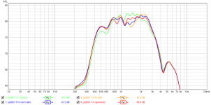
I used some tape on the ja-0801 and measured 1m with a laser distance meter. There were some differences in SPLs so the decay should be taken with a grain of salt.
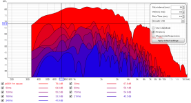
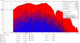
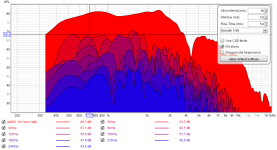
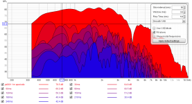
The decay is a fast gate to show what is right off the baffle. The goal is a random 30ms and 300ms.
I was hoping for a clear runaway winner. The tri baffle does a better 2khz-3khz. The aperiodic does a nice 600hz-1khz. The room ratio has a generally nice even decay across the board.
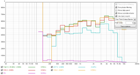
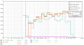
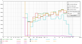
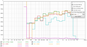
I think what I am looking for can be seen in the RT60: a nice random change between the EDT (-10db down) and what happens at the other decay times. I was surprised the aperiodic has a faster EDT that most at 700hz-1khz.
more info:https://www.roomeqwizard.com/help/help_en-GB/html/graph_rt60.html

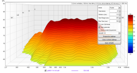

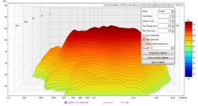
subjective listening observations: I have been listening to music with each baffle with just the ja-0801 playing. With the square baffle, it sounds small and easy to locate. The aperiodic is hard to place the location in the room and sound bigger. This could all be in my head but my decay measurements show the room ratio and aperiodic do have different decays than the square.

I used some tape on the ja-0801 and measured 1m with a laser distance meter. There were some differences in SPLs so the decay should be taken with a grain of salt.


The decay is a fast gate to show what is right off the baffle. The goal is a random 30ms and 300ms.
I was hoping for a clear runaway winner. The tri baffle does a better 2khz-3khz. The aperiodic does a nice 600hz-1khz. The room ratio has a generally nice even decay across the board.


I think what I am looking for can be seen in the RT60: a nice random change between the EDT (-10db down) and what happens at the other decay times. I was surprised the aperiodic has a faster EDT that most at 700hz-1khz.
more info:https://www.roomeqwizard.com/help/help_en-GB/html/graph_rt60.html


subjective listening observations: I have been listening to music with each baffle with just the ja-0801 playing. With the square baffle, it sounds small and easy to locate. The aperiodic is hard to place the location in the room and sound bigger. This could all be in my head but my decay measurements show the room ratio and aperiodic do have different decays than the square.
There is a more complex "Spectre" tile that I am interested in trying out. I made a quick mockup but will need to measure the ja-0801 with some cardboard before going forward with a part. The quick mockup was used to determine if I could even make a laser cut part this large- i can but it won't be cheap.
I just put the tweeter in a random spot. I would like to confirm in vcad the spacing.

more aperiodic tile links:
https://github.com/christianp/aperiodic-monotile
https://cs.uwaterloo.ca/~csk/spectre/
I took another look at the measurements on-axis at 1m:
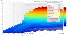
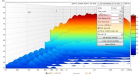
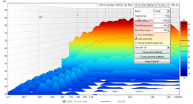
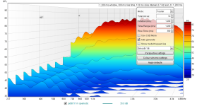
It seems like a very long decay shows the differences. The decay times are much longer than I thought would matter. I might do another round of measuring just to confirm.
The room ratio curve is also something I am still tracing. The aperiodic shape was ready to go thanks to the github files. I am curious how both perform with a flush mounted driver.
I just put the tweeter in a random spot. I would like to confirm in vcad the spacing.

more aperiodic tile links:
https://github.com/christianp/aperiodic-monotile
https://cs.uwaterloo.ca/~csk/spectre/
I took another look at the measurements on-axis at 1m:


It seems like a very long decay shows the differences. The decay times are much longer than I thought would matter. I might do another round of measuring just to confirm.
The room ratio curve is also something I am still tracing. The aperiodic shape was ready to go thanks to the github files. I am curious how both perform with a flush mounted driver.
Attachments
I used inkscape to convert the image to a vector. This worked better than me trying to trace the curves myself. It is pretty darn close. (black lines = raster and the red = vector)
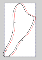
The svg is attached.
more: https://inkscape.org/
This past weeked I measured the dimension of the ja-0801 and have that in a newer baffle design. The spacing is for the XO. I still need to do more in vcad to compare the sims. My gut/experience still likes the idea of a tweeter on a stick so this is going against that.


A vcad diffraction sim: This is a comparison of the tweeter being at the top (orange line) vs bottom section (magenta) of the baffle. I was also interested in how the mid would sim at opposite horizontal positionsnso those are tossed in too.

The svg is attached.
more: https://inkscape.org/
This past weeked I measured the dimension of the ja-0801 and have that in a newer baffle design. The spacing is for the XO. I still need to do more in vcad to compare the sims. My gut/experience still likes the idea of a tweeter on a stick so this is going against that.


A vcad diffraction sim: This is a comparison of the tweeter being at the top (orange line) vs bottom section (magenta) of the baffle. I was also interested in how the mid would sim at opposite horizontal positionsnso those are tossed in too.
Attachments
I did a second round of comparing baffles. I wanted to be sure I was not just looking at the noise floor and did not make a choice from one measurement. So this time I did a second measurement of each baffle to compare and and shaded out everything below -40db in the waterfall.
Only 3 baffles were compared, the Aperiodic (AP), Room ratio (RR), and square (SQ).
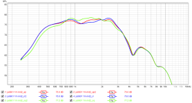
SPL's show the measurements are darn close and the different baffles have different spl's on-axis. I really think much of the difference comes from the size and the interaction with the seas woofer's surround - somewhere around 1.8khz it is bouncing back depending on the baffle.

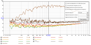
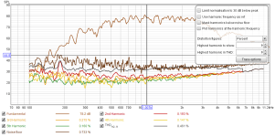
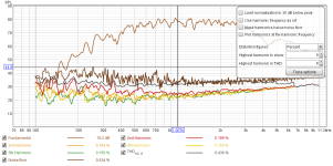
Aperiodic 1&2 vs room ration 1&2 distortion. The noise floor does change a bit between the measurements.
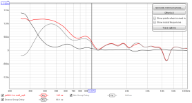
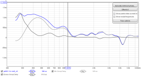
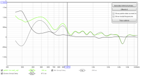
4ms gate GD of the aperiodic vs room ratio vs square
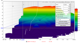
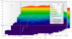
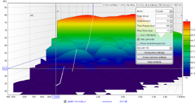
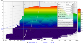
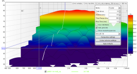

waterfall: Aperiodic 1&2 vs room ratio 1&2 vs square 1&2
The duplicate measurements are very close. It seems like the AP baffle does a nice job with longer frequencies and decays but this could just be because of the size- it is physically taller than the RR. I am now wondering what happens when the AP and RR are roughly the same size. I was hoping for clarity but don't think I have it yet.
Only 3 baffles were compared, the Aperiodic (AP), Room ratio (RR), and square (SQ).

SPL's show the measurements are darn close and the different baffles have different spl's on-axis. I really think much of the difference comes from the size and the interaction with the seas woofer's surround - somewhere around 1.8khz it is bouncing back depending on the baffle.


Aperiodic 1&2 vs room ration 1&2 distortion. The noise floor does change a bit between the measurements.


4ms gate GD of the aperiodic vs room ratio vs square


waterfall: Aperiodic 1&2 vs room ratio 1&2 vs square 1&2
The duplicate measurements are very close. It seems like the AP baffle does a nice job with longer frequencies and decays but this could just be because of the size- it is physically taller than the RR. I am now wondering what happens when the AP and RR are roughly the same size. I was hoping for clarity but don't think I have it yet.
Watching your thread with great interest.This is a new thread started from a rando post here: https://www.diyaudio.com/community/threads/headshakes-far-field-3way.382393/post-7434715
I've had a clean pair of JA0801 Be mid-domes for some years. Plotted lots of plans for them but haven't hatch any yet. 😀
Mine measure much like yours, suspended bare in the middle of the room (22x19 x9' fairly well damped). The huge non-round faceplate is a headache, as it really needs to be rebated to keep diffraction at bay. It also makes close center-to-center with any accompanying tweeter difficult. I considered bare plate-less domes but none of them are great metal domes, never mind beryllium. The SB26ADC might be a good match crossed 5-6kHz.
Unlike a lot of modern tweeters, the dome + VC are affixed to the faceplate.
I finally cut a router template to flush mount the JA0801 but haven't got around to trying it yet. I suspect it's not quite smooth/accurate enough. 🙁
I thought about pulling the grill off so that it can be mounted from the rear in a shallow waveguide cut with something like a 1/2" quarter round router bit. Might still do this.
hi, @silent mike .
I'm using a laser cutting service and building up from layers. I use 0.5mm layers to pad it up so things are sorta flush. Some skewers will hold things together (green holes).
I use dsp so the tweeter does not have to be very close. The tricky part for me is where to place it on the monotile. My early sims showed where to place it on the tile.

To save on the cost, the monotile will be a very thin part (maybe metal). The ja0801 cutout needs a little more work since the lead placement is not quite right. The design is made to act like a facade with a stand in back.
I would like to fuse my perforated baffle project with this one but think the monotile does most of the work for a nice room response. (i still need to test this a bit further).
I'm trying to make 4 different projects at once with one order so it will be a little more time before it shows up.
I'm using a laser cutting service and building up from layers. I use 0.5mm layers to pad it up so things are sorta flush. Some skewers will hold things together (green holes).
I use dsp so the tweeter does not have to be very close. The tricky part for me is where to place it on the monotile. My early sims showed where to place it on the tile.
To save on the cost, the monotile will be a very thin part (maybe metal). The ja0801 cutout needs a little more work since the lead placement is not quite right. The design is made to act like a facade with a stand in back.
I would like to fuse my perforated baffle project with this one but think the monotile does most of the work for a nice room response. (i still need to test this a bit further).
I'm trying to make 4 different projects at once with one order so it will be a little more time before it shows up.
@HeadShake -- Have you seen the metamaterial sound absorber cap for an SB Acoustics tweeter by @Patrick Bateman ? His STL file is here. I 3D printed one to try myself. No chance to mod one of my SB26ADCs yet. If it works to reduce distortion as well as PB says it does, and extends the tweeter's low frequency reach, I'd be totally stoked.
Naturally, I'm eager to make & try a meta-absorber for the JA0801. I don't have the 3D drawing skills yet, so will ask for help from the local FabLab and from other members here.
The back cover of the JA0801 is easily removed, and there's quite a substantial cylindrical hollow under the dome. The cover adds additional volume, which can easily be expanded if necessary, to the diameter of the magnet.
Perhaps you are handy with 3D drawing?
@silent mike a back chamber is on my list of todo's. Getting past the baffle is the first step. I hope to have something to test in the next couple weeks.
Thanks for checking in and sharing Patrick's effort.
This is what is used to calc. a perf. metal plate:
This is from my other thread and I used this on the baffle. I was able to change the decay of a baffle with just a 1cm chamber. There are some modern mids that use something like this behind. the SBA mid and the tang band seem too.

I used the above to help make a stainless steel plate for this baffle. The melamine and chambers are in this pic.

The decay of each plate I tested is at the bottom of this post:
https://www.diyaudio.com/community/threads/headshakes-far-field-3way.382393/post-7105803
Thanks for checking in and sharing Patrick's effort.
I do think some melamine vs stuffing would be interesting. IMO melamine should be spaced away from the wall to work best.The back cover of the JA0801 is easily removed
This is what is used to calc. a perf. metal plate:
This is from my other thread and I used this on the baffle. I was able to change the decay of a baffle with just a 1cm chamber. There are some modern mids that use something like this behind. the SBA mid and the tang band seem too.
I used the above to help make a stainless steel plate for this baffle. The melamine and chambers are in this pic.


The decay of each plate I tested is at the bottom of this post:
https://www.diyaudio.com/community/threads/headshakes-far-field-3way.382393/post-7105803
I took a quick look at the back plate.

It could just be because it is so old, but it looks like the fiberglass is less dense right at the bottom of the cup.
The fastest thing would be just to make a plate that sits near the bottom of the cup. I might try a FS plate and a 3khz plate just to see what happens.
The JA0801 is darn nice as-is so this could all be a waste. When I messed with the visaton SD=22 dome, changing the material made the performance worse.

It could just be because it is so old, but it looks like the fiberglass is less dense right at the bottom of the cup.

The fastest thing would be just to make a plate that sits near the bottom of the cup. I might try a FS plate and a 3khz plate just to see what happens.
The JA0801 is darn nice as-is so this could all be a waste. When I messed with the visaton SD=22 dome, changing the material made the performance worse.
I have to admit I don't understand this perforated plate you're talking about, or the frequency range attenuation chart you posted.The fastest thing would be just to make a plate that sits near the bottom of the cup. I might try a FS plate and a 3khz plate just to see what happens.
If I understand correctly, the Satori mid dome has a mesh type dome directly behind the actual dome. Like just a mm or 2 behind. The rest is acoustic stuffing -- e.g., fiberglass or similar.
I was thinking more along the lines of swapping the ja0801 back cup with a cone like in the Satori mid dome. Maybe stuffed with assorted lengths of thin drinking straws to make a multi-resonance broadband absorber.
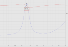
The impedance peak on your Yamaha BE dome is nice & low but seems quite prominent at 26.5 ohms. Surely this could be lowered with mods to the back for some kind of performance improvement.
I'll check the measurements on my pair later.
I'll check the measurements on my pair later.
Found original Dayton DATS files but they seemed corrupted, so ran a fresh set. In stock form, 355 Hz, 23.5 ohms. Slightly different from yours, @HeadShake
1) stock

2) with back open

3) 12" traffic cone against open back

4) traffic cone with poly loosely filled

5) traffic cone with similar amount of long hair wool

Quick observations:
1. The stock 365 Hz Fs is pretty low, but impedance is higher than I'd expect. Perhaps it's because all current tweeters I've measured have ferrofluid.
2. Open back Fs is lowest at 235 Hz. This would seem the lowest Fs we can hope for when the back is closed.
3. With the 12" traffic cone over the open back, Fs rises, as expected, but only to 265Hz, which is less than I expected. Multiple aux peaks above & below look bad.
4. The poly fill helps tame the multiple peaks, brings Fs down to 250 Hz, but peak amplitude is only down a dB.
5. Long teased wool has similar effect to poly, but I did not weigh either, so it might not have been exactly the same amount.
The "seal" between the backside of the driver & the cone was far from perfect -- just placed with a bit of pressure.
Admittedly, a 12" cone on the back of a driver is impractical. I would probably reduce this down to maybe 8" if I decided to use an expanded cavity back.
The big question for me is what an array of varied length thin straws (1/16" to 1/8" depending on length) packed and closed at the far end in such a cone might do. Yeah, a broadband multi-resonant absorption array akin to KEF's "metamaterial".
That experiment will have to come later. Probably best when I have the JA0801 in some kind of viable speaker system.
1) stock
2) with back open
3) 12" traffic cone against open back
4) traffic cone with poly loosely filled
5) traffic cone with similar amount of long hair wool
Quick observations:
1. The stock 365 Hz Fs is pretty low, but impedance is higher than I'd expect. Perhaps it's because all current tweeters I've measured have ferrofluid.
2. Open back Fs is lowest at 235 Hz. This would seem the lowest Fs we can hope for when the back is closed.
3. With the 12" traffic cone over the open back, Fs rises, as expected, but only to 265Hz, which is less than I expected. Multiple aux peaks above & below look bad.
4. The poly fill helps tame the multiple peaks, brings Fs down to 250 Hz, but peak amplitude is only down a dB.
5. Long teased wool has similar effect to poly, but I did not weigh either, so it might not have been exactly the same amount.
The "seal" between the backside of the driver & the cone was far from perfect -- just placed with a bit of pressure.
Admittedly, a 12" cone on the back of a driver is impractical. I would probably reduce this down to maybe 8" if I decided to use an expanded cavity back.
The big question for me is what an array of varied length thin straws (1/16" to 1/8" depending on length) packed and closed at the far end in such a cone might do. Yeah, a broadband multi-resonant absorption array akin to KEF's "metamaterial".
That experiment will have to come later. Probably best when I have the JA0801 in some kind of viable speaker system.
WOW! You've been busy! Thanks for all of the testing!2. Open back Fs is lowest at 235 Hz. This would seem the lowest Fs we can hope for when the back is closed.
It is so neat to see relationship between the resistance and the back cup. On some level I feel like I am blindly sticking my hand inside of a bell I do not understand.
The nomogram image shows the relationship between a throat (plate thickness + hole size), depth of a chamber, and the percent of the open area. The goal is sorta trap a particular frequency by defining the open area of the plate. Energy is lost as heat in the throat. I used this site to find the spacing: https://www.perforated-sheet.com/calculation/how-to-calculate-open-area.html
To really zap 300-400hz the chamber will have to be much larger. Just to try it out I did make a mockup plate that uses the depth of the standard cup. This plate would sit on top and is for around 330hz. I don't expect it to do much since it is a mostly closed plate (only 0.26% open area) but who knows...
Your open back measurement makes me wonder if a 800hz plate would be just as good.
A plate 13mm from the bottom of the standard cup to target around 3000hz is also something I want to try out.
(edit: i really need to double check the placement vs the hole at the back of the driver)
Yeah, that is all beyond me but I did create multi-frequency plate with the baffle and small chambers (image above). The same could be done inside.The big question for me is what an array of varied length thin straws (1/16" to 1/8" depending on length) packed and closed at the far end in such a cone might do. Yeah, a broadband multi-resonant absorption array akin to KEF's "metamaterial".
Keep in mind different materials will have their own curves... some don't absorb low frequencies at all:
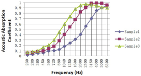
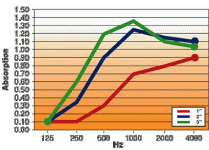
PET fiber vs malamine.
Last edited:
- Home
- Loudspeakers
- Multi-Way
- project: Emperor L26ROY (tweeter + Yamaha JA-0801 + Seas L26ROY)