Hey,
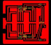
I made pcb using this circuit.
Pre Tone Control Stereo by IC NE5532 -Audio -Electronic Circuits Diagram-Elecpod
When I fire this thing up there is voltage difference between pins 2 and 3 ( and 5 and 6). So there is voltage in the output even there is no input at all and volume is turned to zero. When turning knobs it affects voltages. The lowest voltage is achieved when Volume is anticlockwise, Bass is in the middle and treble is fully clockwise (15mV at the output and 70mV between 5 and 6) . Even then there is BZZZ sound coming out of the speaker. My meter isn't pro one, so it might be that those readings aren't exactly right, but it gives direction.
I think there is two things which could be wrong. First is that my pcb design is not right. Second is that the schematic is wrong.
Can you see or guess what could be wrong?
Attachments
You might want to put a capacitor from pin 4 to ground and from pin 8 to ground.
The Opamp might be oscillating.
Make sure that your +12 volt and -12 volt supplies are delivering clean voltage.
I once designed a circuit using 5532 IC's. I had a similar problem and discovered that my batch of IC's was bad. I temporarily installed 1458 IC's and the problem went away.
I ordered a new supply of 5532's from a different manufacturer and they were good.
Good luck.
You may well have oscillations. Neither the layout given on the same page as the schematic nor your layout are close to ideal. In particular having a long track connected to pin 2 (and pin 6) is asking for instability when an opamp is used at low gains with fairly high resistance feedback as here.
this sounds like a ground reference problem.
Are you sure your pot is connector correctly to ground? And input signal connected correctly to board ground?
Are you sure your pot is connector correctly to ground? And input signal connected correctly to board ground?
Ok. I think I must redo this pcb. I haven't found too many schematics with tone stack. Could you recommend me one? Amplifier I'm using is LM3886 based.
You can AC-couple the output, i. e. put a capacitor in series and a resistor to ground after that. The resistor should be in the range of 100k to 1meg. The capacitor should be chosen according to your desired high-pass filter roll-off.
Or you can look for a better schematic.
Or you can look for a better schematic.
pacficblue negative inputs floating DC-wise
Look again a bit more carefully. There's a perfectly fine DC bias path from pin2 via R3, VR-3 and R2 to the output (pin 1 in this case). But this will depend on the pot wiper not losing contact...
And that is what gives the trouble. The non-inverting input is directly grounded which gives 0 V offset. The inverting input may or may not have a DC path to ground, because that depends on the following amp.
If it has a path to ground (DC-coupled amp or AC-coupled plus terminating resistor before the input cap) there is a DC offset at the inverting input and its difference to the 0 V at the other input will be amplified. What makes it worse is that VR-3 and VR-4 make it variable, so even the possibility to set the DC offset at the non-inverting input to the same value with a resistor won't work well.
If the following power amp does not provide a path to ground (AC-coupled amp without terminating resistor at the input), the inverting input is floating.
Another thing that is not so nice is the possibility to short the source's output as pointed out by mjf in another thread. Volume pot fully open and balance pot to one side means direct path to ground from the corresponding input pin.
The non-inverting input is directly grounded which gives 0 V offset.
I agree that the direct grounding of the +ve input isn't ideal - a series resistor would help to reduce the offset. But that's not what the problem is that the OP is experiencing.
The inverting input may or may not have a DC path to ground, because that depends on the following amp.
Incorrect. As I explained above, it has a DC path to ground via the two resistors and the pot. In fact, only a DC path is necessary, its not required to have it to ground. The 5532 is providing a DC path to one or other of the supply rails via its OPS.
What makes it worse is that VR-3 and VR-4 make it variable, so even the possibility to set the DC offset at the non-inverting input to the same value with a resistor won't work well.
It won't work perfectly, but this is audio, it will work well enough.
Another thing that is not so nice is the possibility to short the source's output as pointed out by mjf in another thread. Volume pot fully open and balance pot to one side means direct path to ground from the corresponding input pin.
Yep - could be fixed with lowish (say 2k) series resistors either side of the bal pot.
I agree that the direct grounding of the +ve input isn't ideal - a series resistor would help to reduce the offset.
No. The resistor needs a value that sets the DC offset at the non-inverting input to a similar value as on the inverting input, if you want low DC offset at the output. That means its value should nearly match the combined resistance to ground at the inverting pin at any moment. How do you match a resistance that is variable by two potentiometers with a single resistor for all possible settings?
But that's not what the problem is that the OP is experiencing.
What is it then?
Incorrect. As I explained above, it has a DC path to ground via the two resistors and the pot. In fact, only a DC path is necessary, its not required to have it to ground. The 5532 is providing a DC path to one or other of the supply rails via its OPS.
You mean, we are wasting our resources on an input resistor to ground when we make amplifiers?
It won't work perfectly, but this is audio, it will work well enough.
Maybe as long as you don't define a minimum quality requirement. The following description shows the influence of that variable DC path to ground and how it does not appear to work well at all. The word 'voltage' is used in the sense of output DC offset here.
Tone controls affect the voltage. Bass full anticlockwise and volume 0 the voltage is 3,3V. Turning also treble to full anticlockwise its 5,3V. If I turn all three knobs fully clockwise voltage is 1,8V. And when Treble and Bass are fully clockwise and volume fully anticlockwise the voltage is 0V. Sound from my test speaker is very BZZZZZZZZ even when there is that 0V from preamp.
hello.
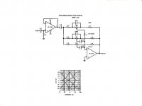
found in an old national datasheet (lf353) a tonecontrol.
if you omit the unity gain buffer at the input and the midrange control - it is similar to schematic post one (swap lf353 to ne5532). but this schematic does not show psu decoupling caps (e.g. 100nf per rail),grounding res, et cetera..........(should be built in).
Attachments
Last edited:
No. The resistor needs a value that sets the DC offset at the non-inverting input to a similar value as on the inverting input, if you want low DC offset at the output.
So - how low an offset do you think is needed?
That means its value should nearly match the combined resistance to ground at the inverting pin at any moment. How do you match a resistance that is variable by two potentiometers with a single resistor for all possible settings?
If you look at the schematic carefully, you'll notice that its only the bass control which has any effect on the DC conditions - the treble pot is AC coupled. Never heard of ganged pots? I don't consider the offset changes to be a real problem here so I'm not going to suggest an extra resistance track to cope with this.
A cursory analysis shows that the impedance seen by the opamp -ve input varies between 20k and nearly 60k. So I would suggest a 39k resistor on the +ve input, bypassed by a cap of 100p. With this resistor the offset will vary by +/- 4mV in a typical case - the input bias current from memory for a 5532 is 0.2uA.
What is it then?
Posts #2,3.
You mean, we are wasting our resources on an input resistor to ground when we make amplifiers?
Nope. How did you get that notion?
Maybe as long as you don't define a minimum quality requirement. The following description shows the influence of that variable DC path to ground and how it does not appear to work well at all. The word 'voltage' is used in the sense of output DC offset here.
That text you quoted shows there's a problem with the OP's original implementation. If you think there's a problem with the schematic, go ahead and demonstrate that but its a very basic error to confuse the map with the territory.
So - how low an offset do you think is needed?
Depends on the application. If the following amp is DC-coupled like many chip amps are, then the offset should be really close to zero all the time.
With an AC-coupled amp the main question is, whether the resulting offset is far enough from the rails to avoid output clipping with high signals.
If you look at the schematic carefully, you'll notice that its only the bass control which has any effect on the DC conditions - the treble pot is AC coupled.
Yet Makk's description tells that the treble pot has an influence on the offset.
Never heard of ganged pots?
What has the construction form of the potentiometer to do with the isue at hand?
A cursory analysis shows that the impedance seen by the opamp -ve input varies between 20k and nearly 60k. So I would suggest a 39k resistor on the +ve input, bypassed by a cap of 100p. With this resistor the offset will vary by +/- 4mV in a typical case - the input bias current from memory for a 5532 is 0.2uA.
± 4mV referenced to what? And how much offset does that give you with regards to ground, i. e. with regards to the non-inverting input?
Posts #2,3.
Funny oscillations that you can adjust with the tone controls to give variable DC offset.
Nope. How did you get that notion?
Isn't that what this means?
only a DC path is necessary, its not required to have it to ground. The 5532 is providing a DC path to one or other of the supply rails via its OPS.
That text you quoted shows there's a problem with the OP's original implementation.
I agree with you there and I suspect that the real problem is that a DC-coupled amp is connected to this tone control circuit.
If you think there's a problem with the schematic, go ahead and demonstrate that
Not with the schematic as such, but with the bad assessment of the audience the publication is aimed at.
Somebody with sufficient technical background to make it work by introducing resistors at either side of the balance pot and adding AC-coupling to the output does not need that schematic, because he could devise one on his own. For all others these measures should either be shown in the schematic and included on the PCB or they should at least be mentioned in the accompanying text.
Depends on the application. If the following amp is DC-coupled like many chip amps are, then the offset should be really close to zero all the time.
With an AC-coupled amp the main question is, whether the resulting offset is far enough from the rails to avoid output clipping with high signals.
All of which is fine, but avoids the question - which if you remember was 'how low an offset do you think is needed?'. Make the call - put up some hard numbers.
Yet Makk's description tells that the treble pot has an influence on the offset.
Doesn't that tell you something? Don't you get the hint from that piece of evidence that the offset might not be being caused by bias currents?
What has the construction form of the potentiometer to do with the isue at hand?
The issue at hand in this case was your earlier question. Which if you don't recall it, was "How do you match a resistance that is variable by two potentiometers with a single resistor for all possible settings?". The answer to it, once I removed the fallacy that there are two relevant pot settings, is 'with another variable resistance which tracks that variable resistance'. Any clearer now?
± 4mV referenced to what?
To the input, as offsets tend to be traditionally specified wrt inputs.
And how much offset does that give you with regards to ground, i. e. with regards to the non-inverting input?
I'll leave that as an exercise for the interested reader to determine. Note that since I have suggested a series resistor in the non-inverting input, its no longer at ground potential.
Funny oscillations that you can adjust with the tone controls to give variable DC offset.
Yep. Why do you think they're funny?
Isn't that what this means?
For the second time, no its not what that means.😀
I agree with you there and I suspect that the real problem is that a DC-coupled amp is connected to this tone control circuit.
Given that you've got this as a hypothesis, how are you going to test it?
Not with the schematic as such, but with the bad assessment of the audience the publication is aimed at.
Somebody with sufficient technical background to make it work by introducing resistors at either side of the balance pot and adding AC-coupling to the output does not need that schematic, because he could devise one on his own. For all others these measures should either be shown in the schematic and included on the PCB or they should at least be mentioned in the accompanying text.
Various flaws in that reasoning. The first is - it works without the resistors either side of the bal pot. Second is that AC coupling the output is not necessary to make it work. I'll stop at two.🙂
All of which is fine, but avoids the question - which if you remember was 'how low an offset do you think is needed?'. Make the call - put up some hard numbers.
Why should I? Are you feeling that this is a competition of some kind? If so, what is the prize for debugging somebody else's bad design?
Doesn't that tell you something? Don't you get the hint from that piece of evidence that the offset might not be being caused by bias currents?
There sure are more flaws than just one. The one caused by the bias currents is sufficient for me to discard this tone control for use with a DC-coupled output. Until the output is AC-coupled any further investigation is a waste of time (to me).
The issue at hand in this case was your earlier question. Which if you don't recall it, was "How do you match a resistance that is variable by two potentiometers with a single resistor for all possible settings?". The answer to it, once I removed the fallacy that there are two relevant pot settings, is 'with another variable resistance which tracks that variable resistance'. Any clearer now?
I just simulated the circuit and depending on the pot settings the output offset varies from 9 to 32 mV. With the 39k resistor you proposed it varies from -9 to 13,4 mV. With a 100k pot ganged to the bass control pot it varies from 9,3 to 15,5 mV. I see no way around AC-coupling the output.
To the input, as offsets tend to be traditionally specified wrt inputs.
Different country, different tradition. Where I live offsets are traditionally referenced to ground.
I'll leave that as an exercise for the interested reader to determine. Note that since I have suggested a series resistor in the non-inverting input, its no longer at ground potential.
Also note that the suggested resistor is a modification that requires a different PCB. Does that mean you agree that the original schematic is not optimal?
Yep. Why do you think they're funny?
Why don't you?
For the second time, no its not what that means.😀
So what does it mean?
Given that you've got this as a hypothesis, how are you going to test it?
The search function on Makk's posts turns up the following.
And the kit is LM3886 from the chipamp.com.
If Makk has not modified the kit, he owns a DC-coupled chip amp with a gain of 33,35.
Various flaws in that reasoning.
I'd rather not call it flaws, but different demands. A tone control where you have to avoid certain combinations of pot settings may be good enough for you. I would not accept that for me. Neither would I expect anybody else to do that.
DC-coupling the unmodified tone control to Makk's amplifier leads to a DC offset at the speaker terminals between 0,3 and 1,07 V depending on the pot settings without taking into account what DC offset will be added by the power amp itself. Good enough for you? Unacceptable for me.
Why should I?
Oh, how funny! How many more irrelevancies are going to be introduced to this thread which is about a single opamp schematic? I'm neither your mother nor your boss, just another diyer so 'should' does not enter in any way. I simply gave a request, an invitation. You've declined the invitation, that's fine by me😀
Are you feeling that this is a competition of some kind? If so, what is the prize for debugging somebody else's bad design?
In answer to your first question, no, clearly this is not a competition. But since you've raised the topic its clear you're feeling it is. I propose to terminate my own involvement in the discussion as I prefer cooperation myself.😀
While I was typing, everything I wrote and more was covered. I'll go back to just lurking for while. 😀
Last edited:
- Status
- Not open for further replies.
- Home
- Amplifiers
- Chip Amps
- Problem with NE5532 based preamp