While I was typing, everything I wrote and more was covered. I'll go back to just lurking for while. 😀
Strange - I got an email containing your post, but when I come to the thread, there's nothing there. Did you lose your edits somehow? If so I can paste your original post back in from the email I received.🙂 You certainly made some good points.
 A couple points: Based on the data sheets the normal input current of the 5532 at 200 nA, which agrees with the 9-32 mV. The LF353 is 50pA typical, which is 4000 times less so the second with would be more acceptable: 2 to 8 microvolts). (My first reaction was should use an FET input opamp) Second point is the voltages originally posted were completely off, suggesting defective opamps (or fakes) and probably oscillation. There is something going on that is not the circuit. Third is that even with 10 mV, the controls will probably be noisy, even with an output coupling cap. BTW I missed the DC path through the bass control originally, but still dislike this circuit. My 2cents.
...I can paste your original post back in from the email I received.🙂 You certainly made some good points.
Thanks, but by the time I'd done typing and thinking, pretty much everything I said was already discussed. I type (and think) real s...l...o...w. 😀
FWIW a couple of observations;
Do the resistances need to be so large? If the connected source can drive 10k, you could reduce the resistances tenfold (multiplying cap values by ten, naturally) which would make the circuit less sensitive to picking up interference, and reduce Johnson noise in the resistors also.
@pacificblue
I just simulated the circuit and...
With a 100k pot ganged to the bass control pot it varies from 9,3 to 15,5 mV.
I think the idea there would be to recreate the whole DC resistance network seen by +in. So you'd put 10k from -in to the wiper, then 10k from one end of the pot to ground. From the other end of the pot is 120k to ground (nearest standard value to 119.4k).
Or use a FET-input IC. But the "normal" DC offset ain't the real issue.
...the voltages originally posted were completely off, suggesting defective opamps (or fakes) and probably oscillation. There is something going on that is not the circuit.
NE5532 are fussy about layout and supply bypassing. If you have a TL072 (or similar) kicking around, you could maybe drop that in. TL072 are a lot harder to upset.
If a TL072 is happy in your circuit that would be a pointer to the problem. I don't do PCBs, but I gather they're difficult to get right. 🙂
The offset issues all go away if you just choose a more appropriate device for the op-amp. How about a low offset fet input dual op-amp like the AD8512, it's cheap, quiet enough, fairly forgiving and with a properly designed circuit will give you vanishingly low offsets with any conceivable setting of the tone controls.
Others to consider would be the BB OPA2132, and better still the OPA2134 - both of which were still available in pdip packages last time I checked. The LM4562 in pdip is another viable choice, although bipolar its input currents are internally compensated. (10nA vs 200nA for a 5532) It's also the current pet darling of the audiophile community. (I use them and they work fine)
Note that the AD8512 is SMD only, however it could be mounted on a brown dog adaptor if the OP is concerned about layout. (I use SMD parts in most of my SS projects but try to avoid ICs smaller than SSOP, and passives smaller than 0805.)
I have not looked at the design, but any time you choose a device that has significant input bias currents and you use them in a circuit where those currents flow through pots you are asking for problems. Most pots will eventually start to make nasty scratchy noises when rotated if you take this design approach.
Last edited:
Do the resistances need to be so large? If the connected source can drive 10k, you could reduce the resistances tenfold (multiplying cap values by ten, naturally) which would make the circuit less sensitive to picking up interference, and reduce Johnson noise in the resistors also.
Okay, I got that wrong. Kind of overlooked that the -in is a virtual ground (opamp in inverting mode). D'oh!
That said, if the input signal never exceeds 2V peak (more than enough to max out a typical LM3886 amp) the tone circuit shouldn't draw much current even if you did so reduce the resistors. Very rough calculations on my part suggest less than 12mA max, but I could easily have got confused again.
So maybe it's still a viable proposition?
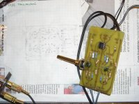
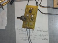
i have built a tonecontrol with parts i had on hand. one channel with pots,the other one with res as substitutes.tested it with ne5532 and lf353,both work........even without psu decoupling caps (but i will not recommend this.....).psu was +-15volts.volume pot 10k at the output.
Attachments
Last edited:
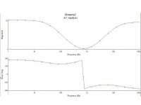
made some sim's.............
the volume pot (big res,100k) has an influence on the gain and frequency response of the circuit (it is an inverted design,the source impedance is added too........).
i think using a buffer amp in front of the input (as shown in post 14 datasheet,or perhaps a b1 ) or a volume pot with a lower res (10k or so) should improve this design.
left picture shows the frequency response with the pots fully turned up........
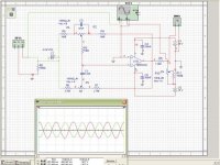
right pic. the schematic.
greets
the volume pot (big res,100k) has an influence on the gain and frequency response of the circuit (it is an inverted design,the source impedance is added too........).
i think using a buffer amp in front of the input (as shown in post 14 datasheet,or perhaps a b1 ) or a volume pot with a lower res (10k or so) should improve this design.
left picture shows the frequency response with the pots fully turned up........
right pic. the schematic.
greets
Attachments
Last edited:
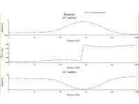
if I read the graph correctly it looks like midband is just over 1V and the extremes are at 10V.
That's a gain of +20dB for the bass and treble.
That seems very high.
That's a gain of +20dB for the bass and treble.
That seems very high.
......indeed,this kind of tonecontrols (post 1,post 14) have a big gain.
i reduced it by using pots with lower resistance (50k,25k,....),here is an example with 50k lin pots.
upper curve fully turned down,the lowest curve was pots fully turned up.
i reduced it by using pots with lower resistance (50k,25k,....),here is an example with 50k lin pots.
upper curve fully turned down,the lowest curve was pots fully turned up.
Attachments
Last edited:
I have already thrown away my pcb. At the end I added only balance and volume control before amp. I have not been missing bass and tone.
But you guys continue, I'm sure this thread will help many DIYers. Maybe somebody would design nice pcb for +- 6 db treble/bass control. That was what I was looking for. I think 6 db is enough.
But you guys continue, I'm sure this thread will help many DIYers. Maybe somebody would design nice pcb for +- 6 db treble/bass control. That was what I was looking for. I think 6 db is enough.
.......can't say at the moment how much boost and cut i need, because i built this just for fun. either i will use it with bigger gain in a musican's project - they often like to create sound effects,more "unlimited"........
or in hifi gear,chip amps,with reduced gain, here is an example with 10k linear potentiometers (and treble - res r6,r7 increased to 3,3k instead of 2,7k).
greetings
or in hifi gear,chip amps,with reduced gain, here is an example with 10k linear potentiometers (and treble - res r6,r7 increased to 3,3k instead of 2,7k).
greetings
Attachments

Last edited:
.......sorry,i am no dj.
i looked into the owner manuals of mixers (yamaha,alesis,.....).
maximum is +-15db around 80.....100Hz (low shelfing).
i looked into the owner manuals of mixers (yamaha,alesis,.....).
maximum is +-15db around 80.....100Hz (low shelfing).
comeing to the end.
probably i will use 10k pots and fetopamps with this tonecontrol.
psu volts were +14,86 -14,79.
changed the 100k tonecontrol pots to 10k: offset at the output is significantly lower,..........e.g. with ne5532 and 100k it was around 8mv ,and with 10k around 2mv;
changed the ne5532 opamp to lf353 (with 100k pots version) ......and the voltdrop at the output decreases.............;
dc-voltdrop changes only if the basscontrol is turned up and down;
the pots are connected to the -inv input of the opamps,so they are a little bit "humm sensitive", i will keep the wire short to the pots.
greetings
Attachments
Last edited:
- Status
- Not open for further replies.
- Home
- Amplifiers
- Chip Amps
- Problem with NE5532 based preamp