Legis,
The phase in my plot is true phase, not min phase (as you know min phase only shows flatness of magnitude dB plot, but nothing of actual phase).
My crossover is kind of stupidly complicated. It uses an alpass network on the tweeter to push phases around and the midrange driver acts like a "filler driver" (which is one way to get linear phase with higher order crossovers).
The design that X showed is an earlier version of what I have now (both were designed using Xsim). Actually, one of the things that got me designing Xsim was to get a way to sim passive crossovers with allpass or non-classical filter shapes because PCD wouldn't support that.
A good advantage of miniDSP is that you can use broadband delays on drivers instead of group delay allpass networks. A disadvantage with miniDSP is that it won't do non-classical filter shapes - I wish they would provide for 2nd order LP and HP filters of arbitrary Q, then you could at least theoretically handle shapes other than Butterworth, Bessel, etc.
After all the effort, I'm not convinced that linear phase (i.e., waveform faithful) is really audible. Having all the sound seemingly coming from a point but with controlled directivity seemed to be the bigger step.
Last edited:
Not to detract from this project, ..but what is its primary objective?
Is it to get point source sound down to 100 Hz (at the cost of directivity and efficiency) ?
Tapping the bandpass midwoofers so close to the mouth (because of the lower response of the full range) can't be adding too much efficiency. On the other hand, (as I just mentioned), you've managed to go down to 100 Hz in a less than optimally sized 100 Hz horn?
Am I missing any other advantages?
Zobsky,
I guess you are asking what is the point of a Synergy because they all have woofer bandpass injection points towards the mouth. The objective is mainly to have a super sensitive low distortion point source horn with good directivity from the 400Hz to 15khz range - and to do so without using a two-way CD and mid driver combo, just a single full range driver. The woofers don't have any horn loading gain in efficiency like the full range does. That is why you need so many of them. But getting that last 400Hz down to 100Hz using inefficient injection ports allows a much more compact horn - and directivity of those frequencies is not important - they are kind of omnidirectional.
I guess you are asking what is the point of a Synergy because they all have woofer bandpass injection points towards the mouth. The objective is mainly to have a super sensitive low distortion point source horn with good directivity from the 400Hz to 15khz range - and to do so without using a two-way CD and mid driver combo, just a single full range driver. The woofers don't have any horn loading gain in efficiency like the full range does. That is why you need so many of them. But getting that last 400Hz down to 100Hz using inefficient injection ports allows a much more compact horn - and directivity of those frequencies is not important - they are kind of omnidirectional.
Last edited:
New Time Alignment
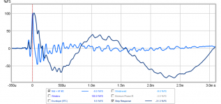
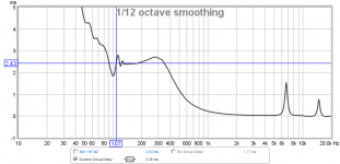
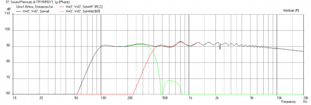
Thanks to Legis for pointing out that I had the mid woofers firing before the full range driver - I got the delay applied on the wrong driver. Anyhow, I did the usual play a tone at XO freq and adjusted delay on inverted phase of the fullrange until minimized, then flipped back. In this case, normal is inverted phase for the fullrange. The delay on the mid woofer ended up at 1.24ms. The step response is no longer negative and excess group delay ends up at 2.43ms at 100Hz. Measurement is at 5in from exit plane of horn and with -32dB fullscale amplitude in REW driving the miniDSP. Measurements on horn no. 2, no. 1 is very similar.
XO setting:

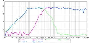
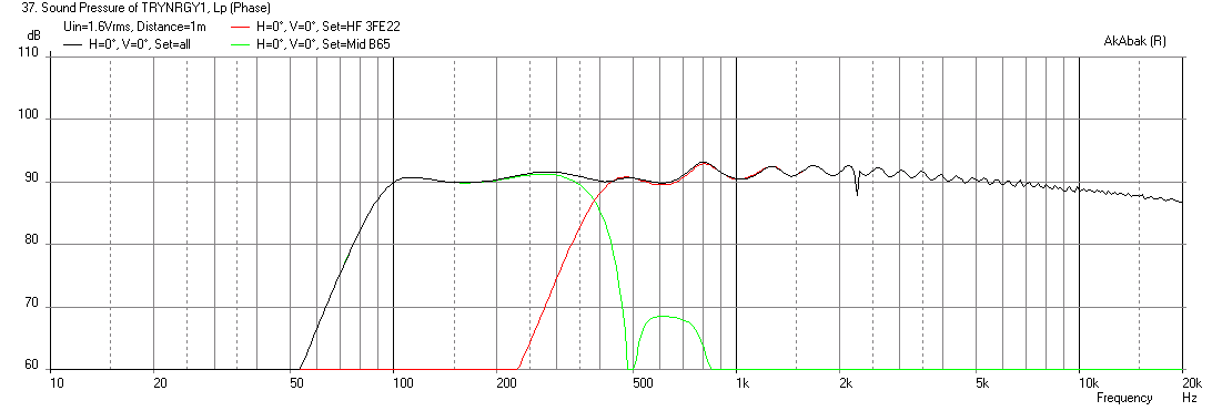
SPL & True Phase (unwrapped):

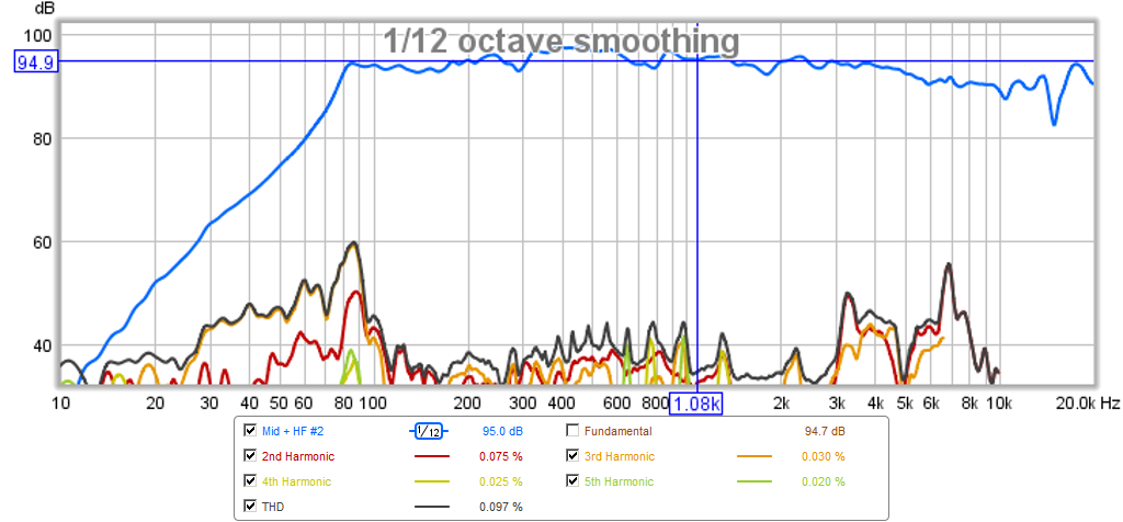
Harmonic Distortion (HD):
Impulse Response (IR) and Step Response (SR):

Excess Group Delay (EGD):
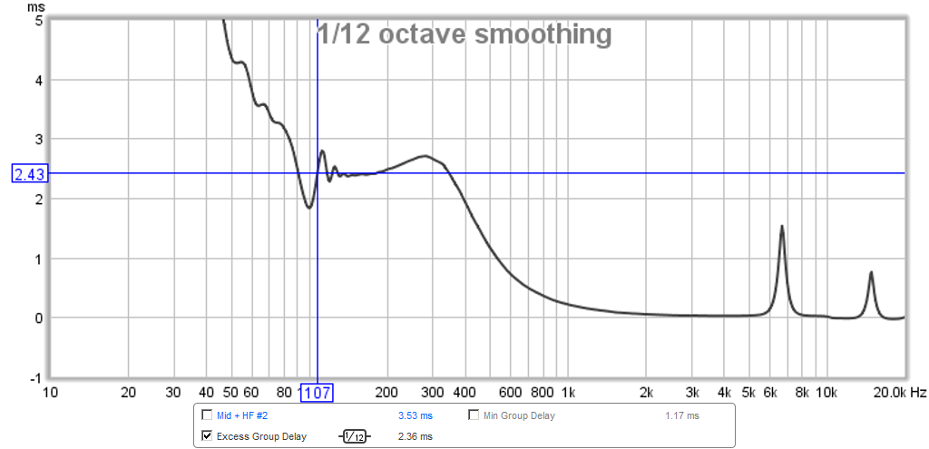
Thanks to Legis for pointing out that I had the mid woofers firing before the full range driver - I got the delay applied on the wrong driver. Anyhow, I did the usual play a tone at XO freq and adjusted delay on inverted phase of the fullrange until minimized, then flipped back. In this case, normal is inverted phase for the fullrange. The delay on the mid woofer ended up at 1.24ms. The step response is no longer negative and excess group delay ends up at 2.43ms at 100Hz. Measurement is at 5in from exit plane of horn and with -32dB fullscale amplitude in REW driving the miniDSP. Measurements on horn no. 2, no. 1 is very similar.
XO setting:
SPL & True Phase (unwrapped):
Harmonic Distortion (HD):
Impulse Response (IR) and Step Response (SR):
Excess Group Delay (EGD):
Attachments

Last edited:
Legis,
The phase in my plot is true phase, not min phase (as you know min phase only shows flatness of magnitude dB plot, but nothing of actual phase).
My crossover is kind of stupidly complicated. It uses an alpass network on the tweeter to push phases around and the midrange driver acts like a "filler driver" (which is one way to get linear phase with higher order crossovers).
The design that X showed is an earlier version of what I have now (both were designed using Xsim). Actually, one of the things that got me designing Xsim was to get a way to sim passive crossovers with allpass or non-classical filter shapes because PCD wouldn't support that.
A good advantage of miniDSP is that you can use broadband delays on drivers instead of group delay allpass networks. A disadvantage with miniDSP is that it won't do non-classical filter shapes - I wish they would provide for 2nd order LP and HP filters of arbitrary Q, then you could at least theoretically handle shapes other than Butterworth, Bessel, etc.
After all the effort, I'm not convinced that linear phase (i.e., waveform faithful) is really audible. Having all the sound seemingly coming from a point but with controlled directivity seemed to be the bigger step.
Thanks for the information bwaslo, you have really done amazing work with the passive crossover and the simulator.
X, still using 8th order filters or something lower in those measurements? I suggest trying 2nd order slopes. Perhaps you could even try 1st order filters if the fullranger can handle the amount of bass coming to it.
I have 24dB (4th order) on the low pass of the woofer and high pass of the fullrange. The woofer has a 12dB (2nd order) on the high pass filter. Is it the EGD that I can get to be lower than 2.43ms at 100Hz if I switch to lower order and reduce overall phase shift? What is your phase shift from 100Hz to 10kHz range?
Zobsky,
I guess you are asking what is the point of a Synergy because they all have woofer bandpass injection points towards the mouth. The objective is mainly to have a super sensitive low distortion point source horn with good directivity from the 400Hz to 15khz range - and to do so without using a two-way CD and mid driver combo, just a single full range driver. The woofers don't have any horn loading gain in efficiency like the full range does. That is why you need so many of them. But getting that last 400Hz down to 100Hz using inefficient injection ports allows a much more compact horn - and directivity of those frequencies is not important - they are kind of omnidirectional.
Thanks much. It's apparent that using a wideband cone driver at the apex of the horn offers the advantage of crossing over to the mid woofers much lower than any normal compression drivers, .. facilitating the implementation of a true 2.1 compact horn system.
Also, why did you pick the tractrix profile, vs the "normal" synergy conical profile? The tractrix obviously offers the benefit of better high frequency compared to a conical horn (at the cost of narrowing directivity at higher frequencies) and probably doesn't need (as much) CD equalization. But in any case, you're using a mini-dsp, so why not just implement a conical synergy and EQ to taste.
... or was this just an experiment that morphed into the success that it is?
Zobsky,
I wanted the tractrix because it has better performance efficiency wise and I wanted the narrower directivity, and it had been shown previously to load a paper cone driver effectively in Bruce Edgar's work. On top of that, a flat wall conical horn synergy has been done already by many folks, and I wanted to showcase the ability of foam core to make a nice curved horn while still having flat top and bottom walls for woofer injection port mounting. After having built many different speaker alignments with foam core, I can now say that there is very little you can't do with foam core speakers. The panel vibration has been shown to be effectively controlled with CLD. Although below 150Hz, I still have some issues and that must be addressed via more mechanical bracing to control the lower freq vibrational modes. This speaker is without a doubt, the lowest distortion, highest sensitivity speaker I have built (or heard). The fullrange cone achieves about 108dB/2.83v and as a result, at regular music levels of sub 90dB, the cone barely moves - and there is barely any distortion as the stroke is so small.
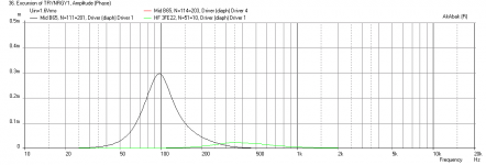
Here is the predicted cone displacement for both the woofer and the 3FE22 at 90dB. The displacement on the 3FE22 is only 23um!
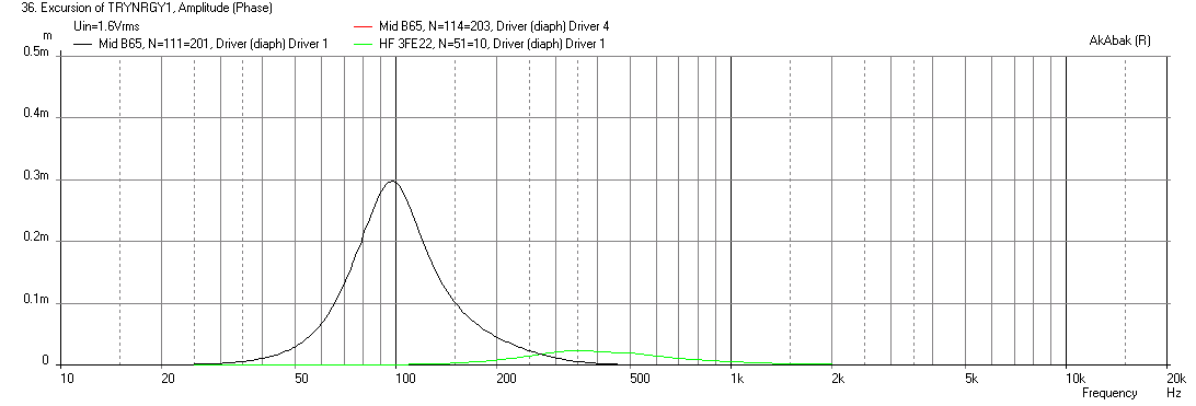
I wanted the tractrix because it has better performance efficiency wise and I wanted the narrower directivity, and it had been shown previously to load a paper cone driver effectively in Bruce Edgar's work. On top of that, a flat wall conical horn synergy has been done already by many folks, and I wanted to showcase the ability of foam core to make a nice curved horn while still having flat top and bottom walls for woofer injection port mounting. After having built many different speaker alignments with foam core, I can now say that there is very little you can't do with foam core speakers. The panel vibration has been shown to be effectively controlled with CLD. Although below 150Hz, I still have some issues and that must be addressed via more mechanical bracing to control the lower freq vibrational modes. This speaker is without a doubt, the lowest distortion, highest sensitivity speaker I have built (or heard). The fullrange cone achieves about 108dB/2.83v and as a result, at regular music levels of sub 90dB, the cone barely moves - and there is barely any distortion as the stroke is so small.
Here is the predicted cone displacement for both the woofer and the 3FE22 at 90dB. The displacement on the 3FE22 is only 23um!
Attachments
Zobsky,
I wanted the tractrix because it has better performance efficiency wise and I wanted the narrower directivity, and it had been shown previously to load a paper cone driver effectively in Bruce Edgar's work. On top of that, a flat wall conical horn synergy has been done already by many folks, and I wanted to showcase the ability of foam core to make a nice curved horn while still having flat top and bottom walls for woofer injection port mounting. After having built many different speaker alignments with foam core, I can now say that there is very little you can't do with foam core speakers. The panel vibration has been shown to be effectively controlled with CLD. Although below 150Hz, I still have some issues and that must be addressed via more mechanical bracing to control the lower freq vibrational modes. This speaker is without a doubt, the lowest distortion, highest sensitivity speaker I have built (or heard). The fullrange cone achieves about 108dB/2.83v and as a result, at regular music levels of sub 90dB, the cone barely moves - and there is barely any distortion as the stroke is so small.
....
[/IMG]
On the last pair of 12 sided ply conical horns I (painstakingly) built, panel
resonance was still an issue around 150 Hz (might have been weak glue joints).
I'm contemplating whether to build something like your project with my 8" tangband W8-1772 ( http://www.tb-speaker.com/detail/1230_04/w8-1772.htm ). This has a rising response (desirable for horn loading).On the other hand, it might be too big a driver (unless I use a small throat and an ungodly compression ratio), considering the commonly available foam core sizes.
I also have a pair of smaller 5" drivers - tangband W5-1880 ( http://www.tb-speaker.com/detail/1230_04/w5-1880.htm ) . These aren't as efficient as their bigger siblings and have a more conventional "flat" response, so I'm nt sure if they'll work as well.
Thoughts?
Off topic but here's a ~ 300 Hz (I ft x 2 ft) paraline line source board that fellow lunatic @kenpeter and I built last night using my trusty PSD2002 compression driver. It obviously doesn't get down to 300Hz as there is no midrange driver in there at teh moment. Apart from that, it works, . and works well.
Attachments
Last edited:
Zobsky,
The way I design the throat is to be about 64% of Sd which puts the apex of the corner at the dia of the surround. This seems to let the HF's that a fullrange cone produces to come through without too much attenuation. I am not sure if you want to use a thin cone driver with whizzer. It is basically cone breakup multiplied by 10. It may work? My guess is it won't get out of the throat very effectively as it is non pistonic. I think a stiff cone and strong motor similar to a CD is desirable. A pro audio driver seems to work well and I would highly recommend the 5in PRV 5MR450NDY that I describe in my previous thread. You may be ok with the 5in TB as the stroke is so small you can EQ the response falloff in the HF more. The scale of an 8in throat horn is huge - not very tractable to build or move. If you want to start with FC, try a small cheap 3incher like the Faital Pro I am using. The build is much easier.
The way I design the throat is to be about 64% of Sd which puts the apex of the corner at the dia of the surround. This seems to let the HF's that a fullrange cone produces to come through without too much attenuation. I am not sure if you want to use a thin cone driver with whizzer. It is basically cone breakup multiplied by 10. It may work? My guess is it won't get out of the throat very effectively as it is non pistonic. I think a stiff cone and strong motor similar to a CD is desirable. A pro audio driver seems to work well and I would highly recommend the 5in PRV 5MR450NDY that I describe in my previous thread. You may be ok with the 5in TB as the stroke is so small you can EQ the response falloff in the HF more. The scale of an 8in throat horn is huge - not very tractable to build or move. If you want to start with FC, try a small cheap 3incher like the Faital Pro I am using. The build is much easier.
Ok, so I finally managed to get some time to work on the first Trynergy of mine today! Fortunately my oldest (nearly 3 years old) daughter wanted to spend time with me, in a way that I could still do stuff! I felt very fortunate!
I glued the top panel on around Tuesday of last week, so today I started to work on the ports. This is what I found:
If you are 3 inches (as xrk791 suggested) inside the front edge of the speaker, the corner of the port shape will be placed around 7.25". The other corner of the port shape appears to land at around 8.25". At some point I'm going to take the curve template xrk971 provided, and match the port to it graphically, and post the result here. That would allow for the top and bottom panels to be pre-cut, before gluing the curved sides, which makes it a lot more difficult in terms of cutting the ports.
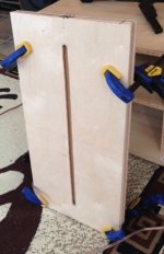
Here are the ports cut out:

Earlier in this thread I incorrectly stated that the thickness of the plywood I'm using is 3/8". It's actually 1/8". So, to combine a layer of damping and to increase the 'chamber' thickness between the driver and the port, I made use of some 7/16" OSB that I had left over from the T18s I've built. Can you tell that I'm a person who likes form over function? 😉
Here is the OSB layer being glued on to one side (I ran out of clamps to do the second this evening). Note the 'seam' in the middle - I miscalculated the original spacing between the drivers, so I had to chop half an inch out of the board.

I hope to get the other side glued up tomorrow, and also fashion the mount for the mid-high frequency driver so I can see what it sounds like!
I glued the top panel on around Tuesday of last week, so today I started to work on the ports. This is what I found:
If you are 3 inches (as xrk791 suggested) inside the front edge of the speaker, the corner of the port shape will be placed around 7.25". The other corner of the port shape appears to land at around 8.25". At some point I'm going to take the curve template xrk971 provided, and match the port to it graphically, and post the result here. That would allow for the top and bottom panels to be pre-cut, before gluing the curved sides, which makes it a lot more difficult in terms of cutting the ports.
Here are the ports cut out:
Earlier in this thread I incorrectly stated that the thickness of the plywood I'm using is 3/8". It's actually 1/8". So, to combine a layer of damping and to increase the 'chamber' thickness between the driver and the port, I made use of some 7/16" OSB that I had left over from the T18s I've built. Can you tell that I'm a person who likes form over function? 😉
Here is the OSB layer being glued on to one side (I ran out of clamps to do the second this evening). Note the 'seam' in the middle - I miscalculated the original spacing between the drivers, so I had to chop half an inch out of the board.
I hope to get the other side glued up tomorrow, and also fashion the mount for the mid-high frequency driver so I can see what it sounds like!
I have 24dB (4th order) on the low pass of the woofer and high pass of the fullrange. The woofer has a 12dB (2nd order) on the high pass filter. Is it the EGD that I can get to be lower than 2.43ms at 100Hz if I switch to lower order and reduce overall phase shift? What is your phase shift from 100Hz to 10kHz range?
Hi X, I get 100Hz - >10kHz around 270deg phase shift total my my setting (only 2nd order high pass for the comp, no LPF or HPF for the mids). It does not change if I apply a 1st order LP filter for the mids.
Yes, lower order filters can//will generate less EGD and phase shift in general.
Last edited:
UnaHM,
Great progress you made there. I would have put the port template on the drawing but it was a prototype build as you go affair for me. Also, the drawing is for a full scale 3.78in throat horn. Thanks for making the updated drawings. Good idea to use OSB for the woofer spacers/CLD panels. What are you gluing it with? Try to use adhesive that is flexible when cured. Your main curved horns made from translucent fluorescent fixture diffusers looks really good. Looking forward to your first sound.
A word of caution for first sound so you don't get discouraged: it won't sound right without EQ.
It may sound unpleasant due to the very exaggerated mids of the 3FE25 having a sensitivity of around 108dB vs the 96dB sensitivity of the woofers in series-parallel. You will have to apply the following EQ at minimum to balance the sound: low shelf of -10dB @4kHz 0.5Q, high shelf +3dB @3kHz 0.5Q. The woofers don't need any EQ. I used a 24dB/oct @375Hz XO and a 12dB/oct @90Hz HPF on the woofers. You will need to experiment with time delays but I found that the fullrange will need about 1.24ms delay relative to woofers and the fullrange polarity needs to be reversed.
With the above basic settings it should sound close. The rest is just cutting any nasty peaks or filling gently some dips circa 700Hz and 3kHz if you find any.
It may be a bit different since you have a 3FE25 and I am using 3FE22 but they are similar.
Good luck!
Hi X, I get 100Hz - >10kHz around 270deg phase shift total my my setting (only 2nd order high pass for the comp, no LPF or HPF for the mids). It does not change if I apply a 1st order LP filter for the mids.
Yes, lower order filters can//will generate less EGD and phase shift in general.
That is amazing that you can get away with a single 2nd order high pass! I should try running the woofers full range and see what happens. I can also run the HF full range driver with a 12dB/oct high pass - I don't think excursion will be an issue. Right now the peak excursion at 90dB with 24dB high pass is 23 microns for 90dB SPL. Which which explains why they don't feel like they are moving at all. Are you using any PEQ's at all to balance the curves or cut peaks/etc? Sounds like to are not whereas I am using those too and I guess each PEQ adds another pole of delay?
That is amazing that you can get away with a single 2nd order high pass! I should try running the woofers full range and see what happens. I can also run the HF full range driver with a 12dB/oct high pass - I don't think excursion will be an issue. Right now the peak excursion at 90dB with 24dB high pass is 23 microns for 90dB SPL. Which which explains why they don't feel like they are moving at all. Are you using any PEQ's at all to balance the curves or cut peaks/etc? Sounds like to are not whereas I am using those too and I guess each PEQ adds another pole of delay?
I also think it is cool. If the unfiltered upper end response of the mids are ragged, then they might be better of with 1st or 2nd order filter.
I think I read somewhere that Avantgarde Acoutics also usually sizes their front chambers/compressions ports so that they can use as little of electrical filtering as possible with some drivers.
Mids do not have eny PEQ filters, they are 100% "raw".
2446J has 5dB high shelf (0,5Q/6kHz) to bring up the HF to balanced sound. There is no resonances/peaks that need EQ'ing/notch'ing. I might try doing the filtering and HF boost with one stroke, using 1-2khz 1st order HPF, to bring down the MF. Then I could omit the PEQ HF boost/high shelf filter completely. With passive approach it would be very adviceable to do it that way, but with active, not so important imo. But to think, 2-way passive xo'ed synergy with only high pass condensator for the comp driver, how ridiculous! 😀
All in all, I think I got VERY lucky.
Last edited:
Well, thanks for the luck Legis! That's good to know, and it simplifies the design of the crossover quite a bit! I'd like to build a passive crossover here, so your results are quite encouraging!
The OSB layer for the second side is now gluing up, so now I've just got to wait for that to cure! I'm hoping with the weather it'll be 4 hours, but the rain might have slowed things down a bit. Hopefully the randomness of the OSB will allow for some damping just by its nature.
The glue I'm using is Loctite PL Premium, as it's what I had left over from building the T18 subs, which cures as a hard material. It might be flexible, but given that it's a construction glue it probably isn't by much 😉
I haven't touched the curved sides yet, but I'm still planning on using braces and hopefully end up with a speaker cabinet that is a cube (hence why I was enquiring about the rear chambers, so that I could fit them into that design), which can sit in a corner and not bother anyone unless I tell them to 🙂
Last edited:
Could this be tempting xrk971, with Rephase GUI build a 375Hz BW 360º anti phase turn FIR filter, make convolution impulse-file for every sampling rate needed and load these to JRiverMC convolution engine. Now should be possible by listening JRiverMC than have zero phaseturn inside Trynergy 2-way bandpass. you could go further eliminate bandpass too but seems to need very errorfree precise response measurements. Think it's quickly done because 4. orden filter in 2-way Trynergy is standard filter therefor quick to build in GUI.
PS unaHm your build progress looks good, we thanks your daughter.
PS unaHm your build progress looks good, we thanks your daughter.
Well, thanks for the luck Legis! That's good to know, and it simplifies the design of the crossover quite a bit! I'd like to build a passive crossover here, so your results are quite encouraging!
Note that Legis built a very different horn (very large conical with 15in drivers and 2in CD) so may not be transferable here... He indeed got very lucky.
- Home
- Loudspeakers
- Multi-Way
- Presenting the Trynergy - a full range tractrix synergy.