That said picture-4 sim for PE 6,5" and the 100Hz GD agree your GD plot, you did a jig for REW some time ago can it measure where real Qtc have landed.
That just may be coincidence with how steep the lower bass range acoustic cutoff is - it falls pretty fast past 90 Hz due to the configuration of the front compression chamber, and size of port. I think a larger port may give me more extended bass for a softer slope plus give me some increased upper bandwidth to keep the acoustic low pass above the electronic XO point. Right now they are about at the same position and it is mostlty dominated by the acoustic falloff.
How do you use REW to measure Qtc of the cabinet? I think in my case, since the sim matches the measurement shape and the sim uses Qtc of 0.5, that may actually be where it is. The rear chamber walls are fully foam lined and there is additional polyfill stuffing, and the foam core walls flex somewhat...
How do you use REW to measure Qtc of the cabinet? I think in my case, since the sim matches the measurement shape and the sim uses Qtc of 0.5, that may actually be where it is. The rear chamber walls are fully foam lined and there is additional polyfill stuffing, and the foam core walls flex somewhat...
Doing the impedance measurements in REW reveal the resonances, thereafter via other simulating programs see what that resonances equal in that used type system Qtc. Those impedance measurements method also good for matching left/right box to same values, add filling to one or the other until impedance measurements nearly same value. DATS unit also use full at this, at same reveal a lot of other parameters and components.
Sorry i'm blank at horn loading therefor can't get PE 6,5" to Qtc 0,5.
In my sealed sim real world achievable lowest Qtc 0,951 (driver Qts 0,95) is whooping 8738 liter and still holds around +1dB spike.
I used to do impedance scans of speakers (and drivers for TS values) with my PC and REW. Worked great until I fried the inputs on the sound card one day when testing a quad sub woofer driver in tapped horn - almost like the reactance caused the line-level input transistors to burn out. I miss having this capability and may get an external USB sound card just to be able to do this again...
Sorry you loosed that lovely audio tool and soundcard input.I used to do impedance scans of speakers (and drivers for TS values) with my PC and REW. Worked great until I fried the inputs on the sound card one day when testing a quad sub woofer driver in tapped horn - almost like the reactance caused the line-level input transistors to burn out. I miss having this capability and may get an external USB sound card just to be able to do this again...
Imagine if a input circuit compensation against oscillation is little hasted through to production state, that REW impedance scans fries such input. This said because DATS software also have oscilloscope and advanced signal generator and if example measuring a capasitor or driver i can switch over to the oscilloscope and see the pulse train visual, this train looks really wide transient hungry and at same it's from DC up to what samling frequency border allow. If budget allow at PE you can get a DATS at 100$ over here cost is 140€ about :-(( 190$.
Installed CLD and woofer mounting plate
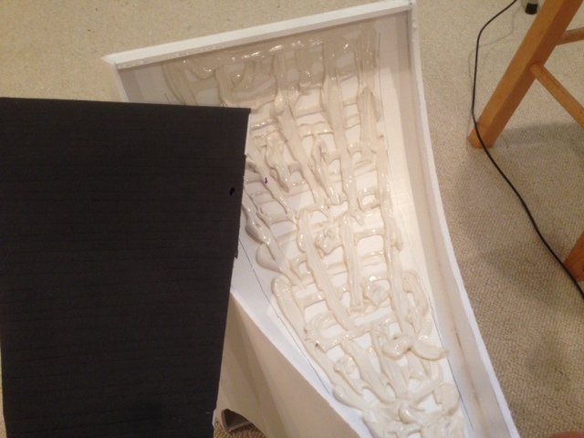
I found a non VOC liquid nails (latex based) and used that instead of caulking. Very important to use non VOC latex liquid nails as the fast drying VOC based one (flammable vapors) will melt the foam in between the paper faces. Now let the thing dry for a few days before cutting the port holes for the woofers.
Liberal dose of latex liquid nails:
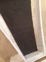
Closeup of CLD top cover with thin cuts to follow curve:

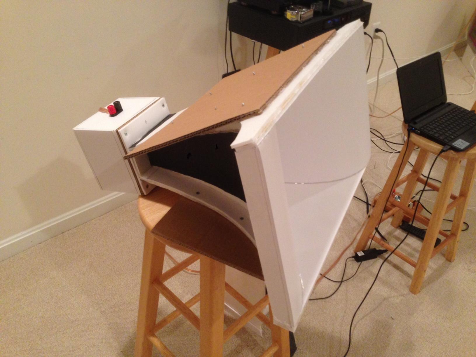
Final horn with CLD and woofer mounting plate (triple layer corrugated cardboard) held on with latex liquid nails and screws:
I always listen to music through the horn as I apply the CLD and can notice that the sound gets cleaner and louder as it is applied. As the latex hardens it improves with hardening from liquid to flexible solid.
I found a non VOC liquid nails (latex based) and used that instead of caulking. Very important to use non VOC latex liquid nails as the fast drying VOC based one (flammable vapors) will melt the foam in between the paper faces. Now let the thing dry for a few days before cutting the port holes for the woofers.
Liberal dose of latex liquid nails:
Closeup of CLD top cover with thin cuts to follow curve:
Final horn with CLD and woofer mounting plate (triple layer corrugated cardboard) held on with latex liquid nails and screws:
I always listen to music through the horn as I apply the CLD and can notice that the sound gets cleaner and louder as it is applied. As the latex hardens it improves with hardening from liquid to flexible solid.
Attachments


Last edited:
Cutout Bass Injection Ports and Installed Woofers
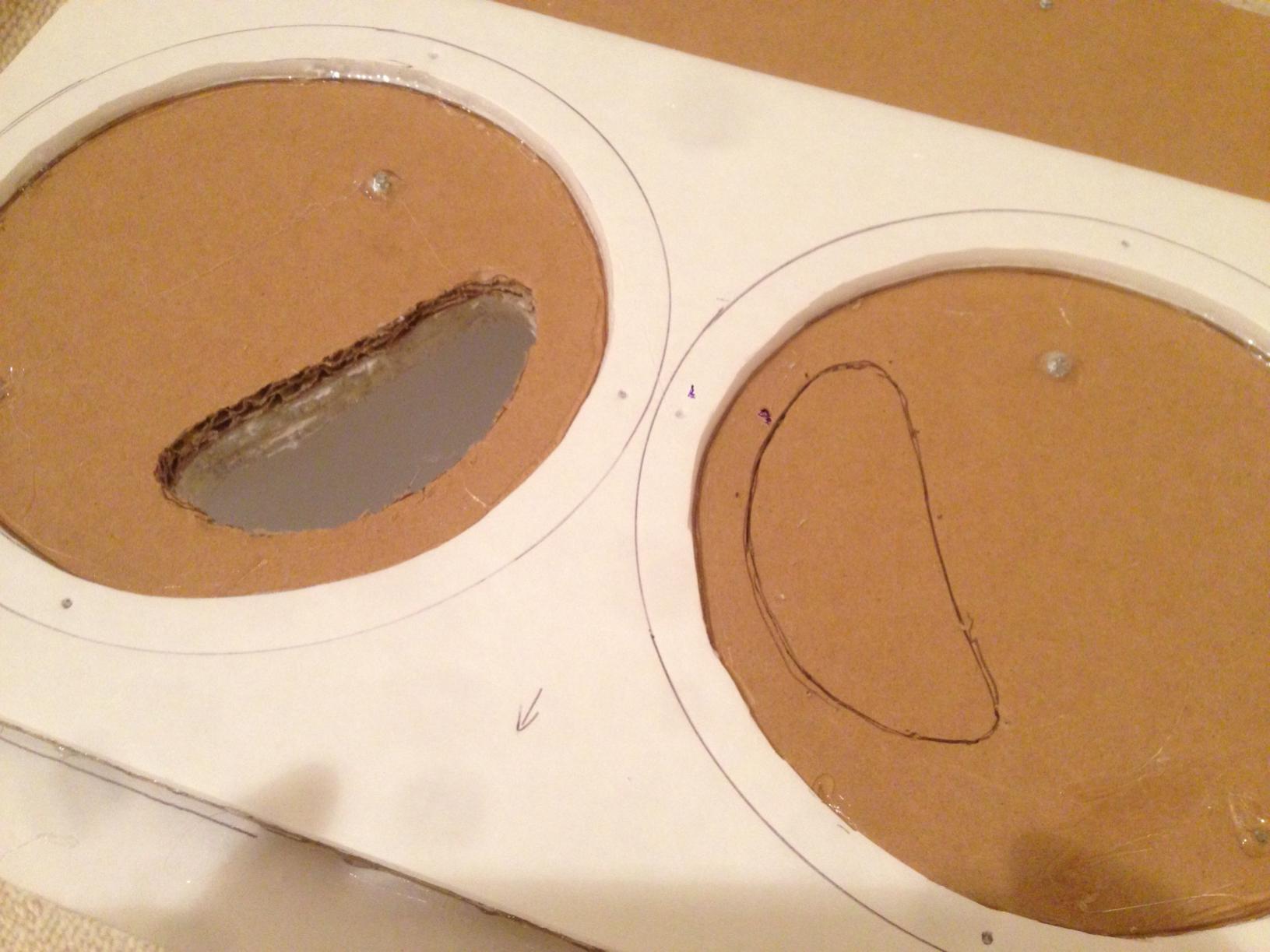
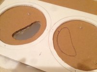
I used a template from unit 1 to transfer the kidney shaped injection ports. This higher quality foam core board was a lot more difficult to cut through. You can see the foam core spacer sheet used to provide clearance for the rubber surrounds from hitting the driver mounting plate.
Cutting out injection ports:
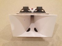
Finished with woofers installed:
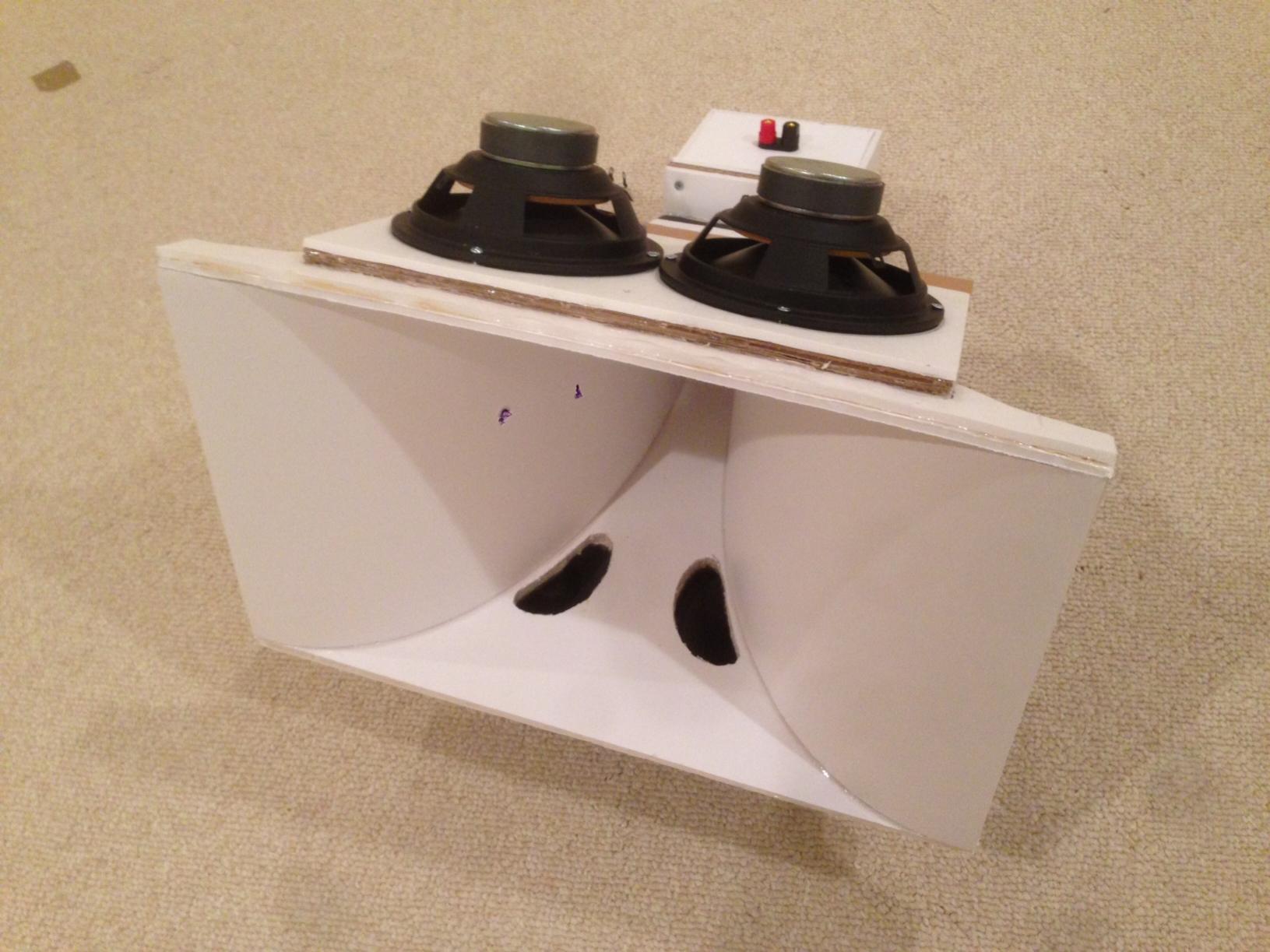
Front view of Trynergy with four PE buyout 6.5 inch woofers installed:

I still need to build a couple of sealed enclosures to cover the woofers...
Stereo Trynergies are a few days away now! Sadly, I do not yet have a second miniDSP or pair of TPA3116D2 amps for a stereo 3-channel. So initial tests will be limited to 2-way operation sans sub woofer. 🙁
I used a template from unit 1 to transfer the kidney shaped injection ports. This higher quality foam core board was a lot more difficult to cut through. You can see the foam core spacer sheet used to provide clearance for the rubber surrounds from hitting the driver mounting plate.
Cutting out injection ports:
Finished with woofers installed:
Front view of Trynergy with four PE buyout 6.5 inch woofers installed:
I still need to build a couple of sealed enclosures to cover the woofers...
Stereo Trynergies are a few days away now! Sadly, I do not yet have a second miniDSP or pair of TPA3116D2 amps for a stereo 3-channel. So initial tests will be limited to 2-way operation sans sub woofer. 🙁
Attachments

Last edited:
Halair,
Hey thanks! My least favorite part of building this speaker has to be cutting and making the rear enclosures. Easy but tedious and involves adding wiring and foam on interior walls. Then once up and running I am going to have to figure out this time alignment and ideal XO slope and location to reduce the group delay.
Hey thanks! My least favorite part of building this speaker has to be cutting and making the rear enclosures. Easy but tedious and involves adding wiring and foam on interior walls. Then once up and running I am going to have to figure out this time alignment and ideal XO slope and location to reduce the group delay.
Agreed, I'm looking forward to hearing the stereo version! 🙂
I should definitely have some time today to work on my version of the project. Not to give you even MORE work to do, but could you scan your template of the port shape you're using, please?
I'd love to match what you're doing! 🙂
I should definitely have some time today to work on my version of the project. Not to give you even MORE work to do, but could you scan your template of the port shape you're using, please?
I'd love to match what you're doing! 🙂
Agree - looks good and hope makes top performance adding stereo to the newer liked Patricia Barber recording "A taste of honey" .
Bass injection port template
Here you go... I align the front edge of the port at 3.0 inches from the mouth in the front. I give about 3/8in spacing from the flat side of the port to the curved wall of the tractrix.
Grid scale is 0.20 inches.
Agreed, I'm looking forward to hearing the stereo version! 🙂
I should definitely have some time today to work on my version of the project. Not to give you even MORE work to do, but could you scan your template of the port shape you're using, please?
I'd love to match what you're doing! 🙂
Here you go... I align the front edge of the port at 3.0 inches from the mouth in the front. I give about 3/8in spacing from the flat side of the port to the curved wall of the tractrix.
Grid scale is 0.20 inches.
Attachments
Agree - looks good and hope makes top performance adding stereo to the newer liked Patricia Barber recording "A taste of honey" .
I like that song too but probably not the best test of stereo imaging. I have some live recordings of a jazz band in a small club that seems to have good spatialization. Dave Brubeck's jazz recordings are also good for this as well as some pop music. I am looking forward to it too but will not have any bass below 90Hz as I don't have a second miniDSP 2x4 in order to implement a stereo 3-way with sub. A lot of stuff doesn't need bass below 80 or 90Hz to be enjoyed though.
Here you go... I align the front edge of the port at 3.0 inches from the mouth in the front. I give about 3/8in spacing from the flat side of the port to the curved wall of the tractrix.
Grid scale is 0.20 inches.
Thanks X. To print it at the right scale, do you know off the top of your head what I should scale that page to?
No, that is what the grid marks are for. I transferred a physically cut piece of cardboard template to the grid paper and scanned it with my phone. You will have to do it by trial and error or just hand sketch based on my drawing - not critical.
Ok. Well, once I've worked it out, I'll let everyone know!
Edit: Is the width of the shape 1.4 or 1.9 inches?
Edit: Is the width of the shape 1.4 or 1.9 inches?
Last edited:
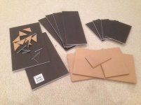
Rear chamber enclosures for woofers made
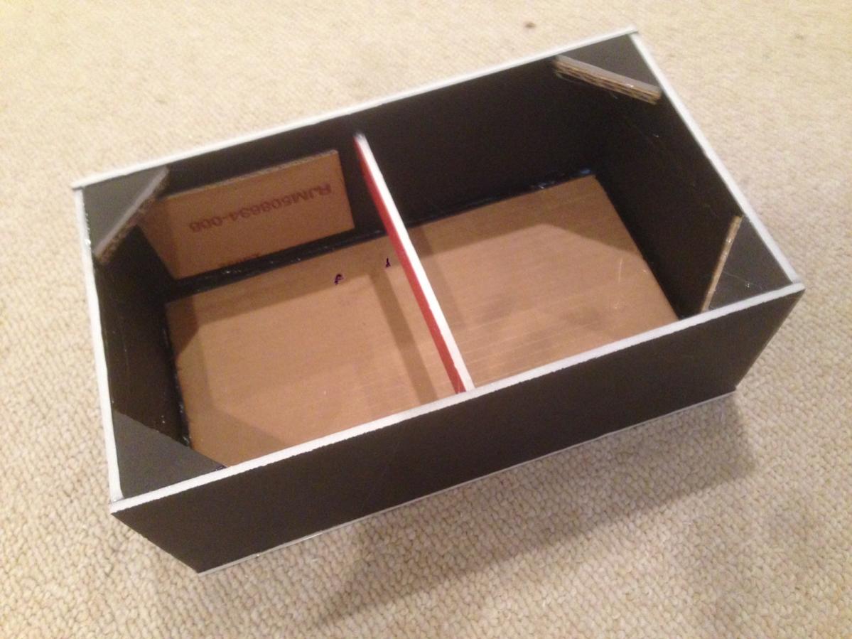
That's a lot of little pieces to cut and glue, now you know why I hate making prismatic boxes. They are done at least and lined with foam. Still need to install binding posts and connect wires to drivers with crimped quick connects. Boxes are 14 in wide x 8 in deep x 5 in tall.
All pieces cut and ready for gluing (2 sets):

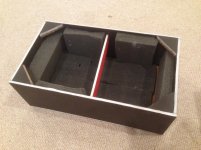
Completed box prior to foam installation:
Grey open cell foam now installed:
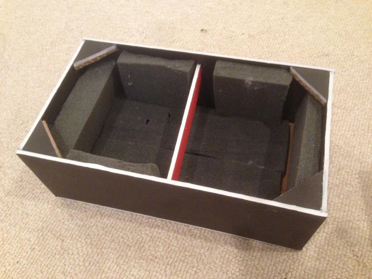
I did this for two boxes.
That's a lot of little pieces to cut and glue, now you know why I hate making prismatic boxes. They are done at least and lined with foam. Still need to install binding posts and connect wires to drivers with crimped quick connects. Boxes are 14 in wide x 8 in deep x 5 in tall.
All pieces cut and ready for gluing (2 sets):
Completed box prior to foam installation:
Grey open cell foam now installed:
I did this for two boxes.
Attachments

Last edited:
Fun! 🙂
In the meantime, I've been tracing and resizing the port template. Here it is:

I'm not sure if this is the full size one or not (it depends on what Google wants to do...), but I hope this is of use! I'll print it out and see 🙂
I also have it available as an SVG, which makes scaling easier. This picture should be 100DPI though, but if not, resize it to 850x1100 at that resolution!
In the meantime, I've been tracing and resizing the port template. Here it is:
I'm not sure if this is the full size one or not (it depends on what Google wants to do...), but I hope this is of use! I'll print it out and see 🙂
I also have it available as an SVG, which makes scaling easier. This picture should be 100DPI though, but if not, resize it to 850x1100 at that resolution!
unaHM,
Thanks for doing that but there is something off with your drawing. Compare it to my PDF and the aspect ratio seems to skinny. Not that it matters much but just saying it's not the same. Something with your graphical program seems to have changed it. Just looking at 1.4 in which is about 1.5 in, the 3.0in is clearly longer and closer to 3.5in.
Thanks for doing that but there is something off with your drawing. Compare it to my PDF and the aspect ratio seems to skinny. Not that it matters much but just saying it's not the same. Something with your graphical program seems to have changed it. Just looking at 1.4 in which is about 1.5 in, the 3.0in is clearly longer and closer to 3.5in.
- Home
- Loudspeakers
- Multi-Way
- Presenting the Trynergy - a full range tractrix synergy.