Forgive my likely ignorance, but I have been reading a little bit of this thread http://www.diyaudio.com/forums/multi-way/151376-homster-how-i-learned-how-fix-horn.html and I am wondering if the tractrix is the right horn for the job here. I just think there must be an awful lot of diffraction in the space between the driver and the horn?
Also on that note, how much space should there be between the faital driver and 2" hole leading into the horn? (is this called the throat?) is it a little box of x liters or is the driver right up against it?
Kinda ties in with my last question about the ports,
Thanks
Also on that note, how much space should there be between the faital driver and 2" hole leading into the horn? (is this called the throat?) is it a little box of x liters or is the driver right up against it?
Kinda ties in with my last question about the ports,
Thanks
Ra7 : links of the plans are on the first post.
Those pdf are drawn for 5.1/4 driver; if you want to use it with a 2" cone like the Scan Speak 10F, just print it with multi-pages printing to scale 1 and reduce the 100% to 66% to have a 2" throat size (instead 2.8").
The new littliest horn is an other scaling if this is what you're asking...
Correct. But test one page of the tile prints at the scale interested in and measure with a ruler to see if manual adjustment needed. Printers may not all print actual dimensions like a CAD flat bed printer. I found 0.70x was needed on mine for the 2in throat. For the smaller micro Trynergy, I used 0.48x scale.
Then tape the tiles together using the alignment marks on the grid.
Forgive my likely ignorance, but I have been reading a little bit of this thread http://www.diyaudio.com/forums/multi-way/151376-homster-how-i-learned-how-fix-horn.html and I am wondering if the tractrix is the right horn for the job here. I just think there must be an awful lot of diffraction in the space between the driver and the horn?
Also on that note, how much space should there be between the faital driver and 2" hole leading into the horn? (is this called the throat?) is it a little box of x liters or is the driver right up against it?
Kinda ties in with my last question about the ports,
Thanks
You are correct about the 2in horn throat causing diffraction/cancellation - it is source of 7kHz dip and reason we are working on phase plug to reduce that. The tractrix refers to the expansion profile. You always have a throat and it is 2in to be smaller than the driver diaphragm to have some compression. I may even try the 10F with the 1.38in x 1.38in throat for more compression and to move the cancellation dip higher up beyond 7kHz where it will be less noticeable. A round throat may help but harder to diy out of lat panels. Putty can be used in corners of square throat to smooth it round and that DOES help if you measure it before and after.
But why not just do a conical horn (easier to build, more constant directivity, less abrupt expansion change)?
Considering how much the small drivers beam, a conical won't have any wider HF dispersion compared to the beaming Tractrix, which has better low frequency response than a conical of similar size/dispersion, reducing excursion and power demands by comparison.But why not just do a conical horn (easier to build, more constant directivity, less abrupt expansion change)?
But the Synergy concept is to match the port entry points to where expansion rate matches loading requirements for the frequency bands being injected, which works out nicely with conical. Does that still hold with a tractrix (expansion rate increases more as you move away from throat, where lower frequencies would want it to be less)?
(I guess the distortion measurements show it probably does, though would be nice to see a comparison with an equivalent conical)
(I guess the distortion measurements show it probably does, though would be nice to see a comparison with an equivalent conical)
Fwiw with a CAD file I can also print a phase plug. But it will be some time still before I can test it. lol.
Correct. But test one page of the tile prints at the scale interested in and measure with a ruler to see if manual adjustment needed. Printers may not all print actual dimensions like a CAD flat bed printer. I found 0.70x was needed on mine for the 2in throat. For the smaller micro Trynergy, I used 0.48x scale.
Then tape the tiles together using the alignment marks on the grid.
I don't know why it is 66% with my A4 paper and laserJet ! but I have 5.1 cm : it is more or less 2" after I checked !
You are right : people have to check it after printed !
I may even try the 10F with the 1.38in x 1.38in throat for more compression and to move the cancellation dip higher up beyond 7kHz where it will be less noticeable. A round throat may help but harder to diy out of lat panels. Putty can be used in corners of square throat to smooth it round and that DOES help if you measure it before and after.
🙂 : thanks for the tip !
Does the low end stay the same ?
From Nate's Mini Synergy thread:
Just want to throw this out here again, is there any special potential worth examining with this? HiWave BMR12 Compact 2" Full-Range Square Speaker 12W 8 Ohm
There is no ideal waveguide shape for this type of radiator. How much problems one will have with a "fudge" I don't know.
A flat disk is the perfect source for an OS waveguide. There are flat disk drivers out there. I know, I was recently asked if one from Parts Express would work in a waveguide. It was a flat disk diaphragm with Balanced Mode Radiator (BMR) drive (which just means that the voice coil drives it at its first nodal ring.)
Just want to throw this out here again, is there any special potential worth examining with this? HiWave BMR12 Compact 2" Full-Range Square Speaker 12W 8 Ohm
I even considered a much more capable Tectonic Elements BMR but just did not like how it sounded as an open radiator.
Certainly cheap enough to try.
Certainly cheap enough to try.
I even considered a much more capable Tectonic Elements BMR but just did not like how it sounded as an open radiator.
Good to know.
Horizontal polar of uTrynergy w/ W2-852SH
Taken at 1.0m. Note that response seems peakier than previous measurement in vertical orientation at 0 deg. I am hypothesizing that it may be because the liquid nails adhesive between the two layers of foam core hardened and the walls are stiffer. Or it may be that the curved wall does not flow into the flat baffle of the speaker that it sat on so there is an abrupt edge for diffraction (probably more likely - can be tested by flipping back to vertical to see if same). Seems more uniform of a behavior up to 12kHz.
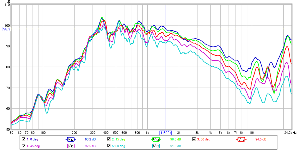
Taken at 1.0m. Note that response seems peakier than previous measurement in vertical orientation at 0 deg. I am hypothesizing that it may be because the liquid nails adhesive between the two layers of foam core hardened and the walls are stiffer. Or it may be that the curved wall does not flow into the flat baffle of the speaker that it sat on so there is an abrupt edge for diffraction (probably more likely - can be tested by flipping back to vertical to see if same). Seems more uniform of a behavior up to 12kHz.
Attachments
Last edited:
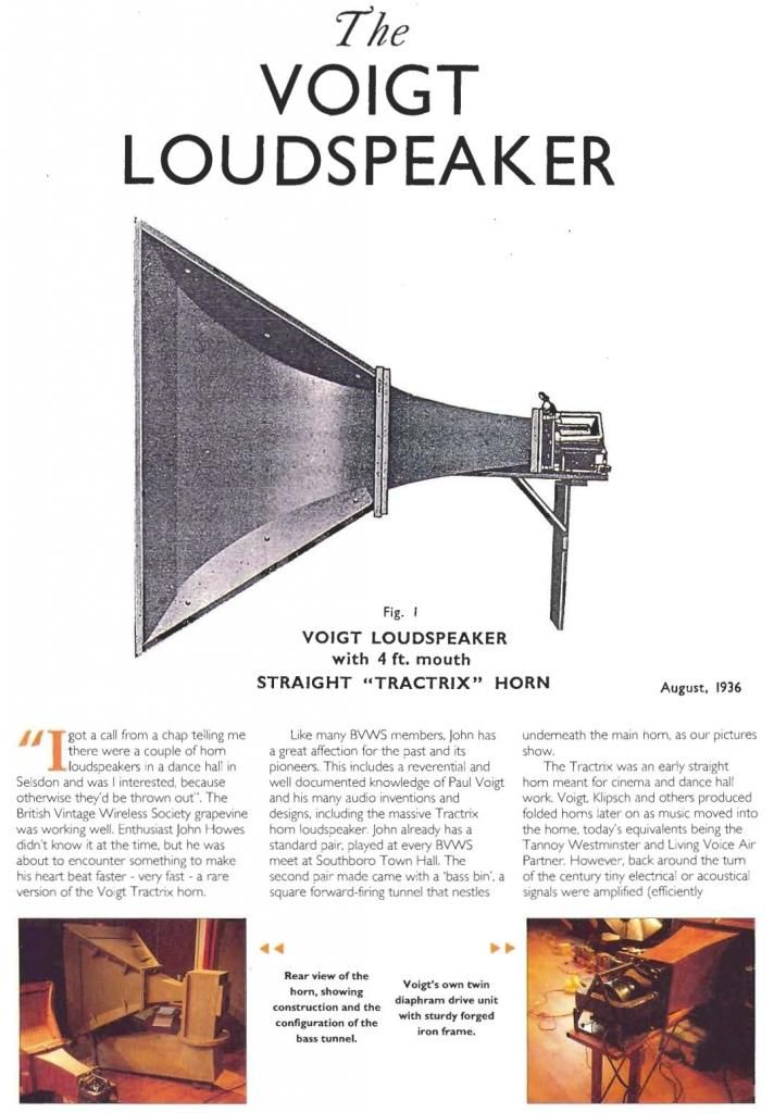
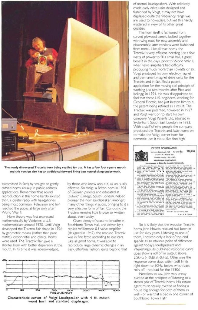
I just ran into these old pix of Tractrix horns driven by fullrange cones (though no Synergy woofers). So, some history, here!
(link: pink fish media - View Single Post - Western Electric's first hifi speaker
these are Voight horns, not Western Electric as the link's name suggests
An externally hosted image should be here but it was not working when we last tested it.
An externally hosted image should be here but it was not working when we last tested it.
(link: pink fish media - View Single Post - Western Electric's first hifi speaker
these are Voight horns, not Western Electric as the link's name suggests
Last edited:
Thanks for the history Bwaslo. I know how efficient they are first hand. Just a few watts is all you need and the dynamics are amazing.
+1 if you read the patent he's talking about conical horns. He briefly mentions that other profiles can be used with the concept but IMO that's just a CYA clause to keep other manufacturers from from building a Tractrix or Expo Synergy.But the Synergy concept is to match the port entry points to where expansion rate matches loading requirements for the frequency bands being injected, which works out nicely with conical. Does that still hold with a tractrix (expansion rate increases more as you move away from throat, where lower frequencies would want it to be less)?
(I guess the distortion measurements show it probably does, though would be nice to see a comparison with an equivalent conical)
If I understand correctly, a conical horn has a variable flare rate (which is what makes the Synergy work as well as it does) and a traditional horn has a fixed flare rate.
That said, I wonder if a trad horn profile would give us more freedom in the port placement (keeping in mind the 1/4wl reflection and horn length for lf loading if needed) since the flare rate is already determined?
I also wonder if a trad profile would better satisfy the requirement that the mid taps into a circumference that's larger than the largest hf wl which is said to help "hide" the ports from the hf output. I could see that working - to an extent - with a horn that has increasing directivity but I don't buy it with a conical horn.
Just thinking out loud here and with my basic knowledge of horns perhaps I'm way off base [emoji6]
Perhaps off topic but I am so impressed with the small horn mounted full range measurements, what do you think about mounting a couple 10f onto the 18 sound 1.4 inch CD horns:
18 Sound XT1464 Constant Coverage HF Horn (1.4 Throat)
Strikes me you could cross at 500hz to a 15 inch and potentially have a very nice 2 way for not stupid money. How do you think it would work with the 1.4 inch throat?
18 Sound XT1464 Constant Coverage HF Horn (1.4 Throat)
Strikes me you could cross at 500hz to a 15 inch and potentially have a very nice 2 way for not stupid money. How do you think it would work with the 1.4 inch throat?
NateHansen66, does it meam the distance between the apex and the ports is correled with the band pass XO of the mid-woofs radiating in the horn?
Got my 10F/84 today ! : Pretty little units 🙂
Speaking about horn : we may put the horn in another one with the sub woof at the apex of the outside horn and behind the sealed cabinet of the inner first horn : one can putt the subwoof : 15" or 18" as it's radiating mainly far from the center of the cone !
If the space between the 2 horns' walls at the mouth is 1" : it could be enough and even have the effect of a sloated bass ! We may have also a very low bass radiating at 2Pi (or cardioid) instead 4Pi in the first meters after the mouth ??
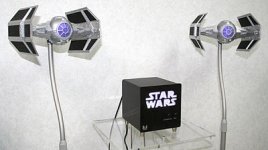
Like the Sphere from Cabasse ! See the ports !
If it's Tratricx into an other one, I call it : the Cube ! You can imagine for instance the horn of Baswlo but with a vented port around it at the edge of the mouth (like the ports of an Onken e.g.)... Sort of Grand'Ma Westminter speaker but more cubic !
PS : the second picture was the strike-back of a speakers-maker, but it didn't work !
Got my 10F/84 today ! : Pretty little units 🙂
Speaking about horn : we may put the horn in another one with the sub woof at the apex of the outside horn and behind the sealed cabinet of the inner first horn : one can putt the subwoof : 15" or 18" as it's radiating mainly far from the center of the cone !
If the space between the 2 horns' walls at the mouth is 1" : it could be enough and even have the effect of a sloated bass ! We may have also a very low bass radiating at 2Pi (or cardioid) instead 4Pi in the first meters after the mouth ??
Like the Sphere from Cabasse ! See the ports !
If it's Tratricx into an other one, I call it : the Cube ! You can imagine for instance the horn of Baswlo but with a vented port around it at the edge of the mouth (like the ports of an Onken e.g.)... Sort of Grand'Ma Westminter speaker but more cubic !
PS : the second picture was the strike-back of a speakers-maker, but it didn't work !
Attachments

Last edited:
- Home
- Loudspeakers
- Multi-Way
- Presenting the Trynergy - a full range tractrix synergy.