Here are my readings so far with inputs shorted to ground
Power Talema 15vac trafo then paired with VRDN psu for +15V/-15V
R6 - 865mv
R11 - 866mv
R106 - 779mv
R111 - 780mv
Voltage divided by 2.7ohm shown in ( )
R24 - 56mv (20.7mA)
R25 - 57mv (21.11mA)
R124 - 49mv (18.14mA)
R125 - 49mv (18.14mA)
R5 - 1.510v
R10 - 1.496v
R105 - 1.428v
R110 - 1.423v
Thanks
Power Talema 15vac trafo then paired with VRDN psu for +15V/-15V
R6 - 865mv
R11 - 866mv
R106 - 779mv
R111 - 780mv
Voltage divided by 2.7ohm shown in ( )
R24 - 56mv (20.7mA)
R25 - 57mv (21.11mA)
R124 - 49mv (18.14mA)
R125 - 49mv (18.14mA)
R5 - 1.510v
R10 - 1.496v
R105 - 1.428v
R110 - 1.423v
Thanks
Attachments

It should be OK. You may tune Q1- Q4 current by R9/109. Yes I use the plastic shaft extension for the pot. It avoids induced voltages when touching the knob and potential buzz. The effect is measurable and potentially audible.
Currently I am using R9/109 as 270R and what do you suggest based on my above readings to change this value to?It should be OK. You may tune Q1- Q4 current by R9/109.
R1,101 used 8k2 and R2,102 used 2k7 per the BOM suggestion.
Thanks
Gain linearity with respect to input voltage (+/-2V which corresponds to +/-10V output) and load resistance from 50 ohm to 1kohm

More on linearity topic in this thread.
More on linearity topic in this thread.
Usual node voltages for JFETs with Idss = 8mA

I can recommend using shoulder washers in an 8mm size if you prefer to use a metal extension rod.Thanks @Vunce I hope you receive the package soon.
I am searching on how to mount the alps pot to the front panel knob without making any contact with the chassis. I have the potentiometer shaft extension kit but that comes all in steel and 300mm long Aluminium rod. The coupler is also aluminium so in order to isolate the pot to the chassis I need to either use a non-metal coupler or a plastic rod.
Thanks @PMA and yes I have the R8/108 as 100R. Now changed R9/109 to higher value but it’s dropping the voltage very less. So when I removed both the R9/109 keeping it open I get exact 1.226v across R5/105.And R8/R108 value? 100R?
I would increase R9/109 a bit to get about 1.25V across R5 and R10, but as I already said, it is not so critical. The recommended scenario is to start with R9/109 unconnected and to select them by measuring voltage drop.
Attachments
It’s making music and pairing with FSSA amp and then AN39. So far pretty good with AN39 clean and clear sound stage.
Thank you @PMA for sharing this design and this is one of the very good line stages one can build super simple
Thank you @PMA for sharing this design and this is one of the very good line stages one can build super simple
I would like to note that voltages measured across the resistors are not so critical. In my last sample, which uses stock LSK170C/LSJ74C, I measure this:

and both channel measure almost same distortion plots.
However, please keep in mind what I write in the manual:
This says that R8 must be selected according to JFET Idss range, to make it able to set appropriate idle current of the input JFET quadruple. This is important. As I have used parts with Idss > 16 mA, I had to use R8 = 200R in my last preamp sample.
and both channel measure almost same distortion plots.
However, please keep in mind what I write in the manual:
R8 value is 100R for Idss 5 – 9mA, 150R for Idss 9 – 12mA and 200R for Idss 12 - 20mA.
This says that R8 must be selected according to JFET Idss range, to make it able to set appropriate idle current of the input JFET quadruple. This is important. As I have used parts with Idss > 16 mA, I had to use R8 = 200R in my last preamp sample.
Hi Pavel, can you explain R17/R119, what is the benefit, compared to classic ccs, with led or diode string as voltage reference?
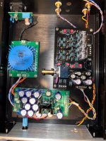
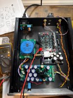
Current progress of my Dispre.. doesn't look like much but it's taken some patience and effort to get the form, fit, and function to my satisfaction here. I'm keeping that raw DC supply a secret. It's very definitely not driving an umbilical and that's very definitely not a Pearl 3 circuit board at the back... my DiyA membership card could get revoked. PMA forgot my ZT15VA PS so I'm stuck having to use a UDP3 and Superreg's for power 🙂 ... Next up power transformer and +/-15V reg mounting..
Attachments
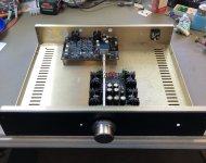
Proper planning is often the most time consuming step for a project, especially for aesthetics. Boards that have a fixed volume pot and in/out connector locations are even more of a challenge.
Nicely done William2001 😉.
Nicely done William2001 😉.
Vunce - Yes I wanted to take advantage of the board mounted XLR's the designer intended, eliminate some wiring and get that clean look. I'm all for XLR's, even with SE use because of my previous bad experiences with poor RCA connections causing frustration and sailor vocabulary. The Neutrik NC3MD's are two separate pieces, so that took some thought about how get everything perfectly lined up and mounted securely. All while making sure the volume control extension was also perfect as possible to not have any binding. And all of that into an already existing chassis (Par-metal 20 Series) that was hacked up for an old DAC project from ~10 years ago. I certainly make no claims about being a metal working wizard, but I think I achieved my goal here. I made a small modification on the raw DC supply to allow the shaft a clean path. I have an Antek toroid with the optional steel cover that will live up in the corner to keep the noisy stuff as far forward as possible.
Last edited:
Boards that have a fixed volume pot and in/out connector locations are even more of a challenge.
Remember you can always use universal joints and extension shafts like the Japanese did for decades with their upper tier HiFi where they wanted the control at the rear (or wherever) and the actuator on the front escutcheon.
Plenty on Ali.
- Home
- Source & Line
- Analog Line Level
- Preamplifier Dispre 2 - JFET