Balanced version, THD and THD+N at 1kHz/4Vrms

THD vs. frequency (at 4V, @BW90kHz) is now mostly a copy of the measuring system plots.

THD vs. frequency (at 4V, @BW90kHz) is now mostly a copy of the measuring system plots.
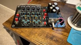
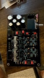
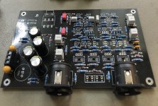
Several shots of design creations of my similar headphone amp design - that never went into production 😉.


I find 10k totally adequate input impedance. All the digital sources can drive it without rise in distortion. CD players or DVD players can drive it easily as well. The only exception might be valve common cathode output. But .... why in such case to use this preamp?
You may of course use 100k input dual pot, if you like, and increase R4/R104 to 1M (and R1/R2/R101/R102 increased 10x, if used). You will have 100k input impedance then. With the only difference against the original design - you will get higher noise and less flat amplitude response, and probably slightly higher distortion. It is up to you.
In my design philosophy, I do not agree with such solution.
I get your point, but the counter example you gave is a bit extreme. In my current calc, I have R1 == 12k, R2 == 68k and a 47k log pot. That gives about 31k input impedance. You think the noise will really be significantly raised?
My 10k BOM pot recommendation is the best compromise from my point of view. I would even like to go to 5k.
You are of course free to make any pot impedance choice you like. D2 JFET as designed (10k pot) has input related noise of 1.2uV/BW22kHz. In your case, it will be 2.1uV/BW22kHz (worst case calculated for 47k/4). In most cases negligible difference.
You are of course free to make any pot impedance choice you like. D2 JFET as designed (10k pot) has input related noise of 1.2uV/BW22kHz. In your case, it will be 2.1uV/BW22kHz (worst case calculated for 47k/4). In most cases negligible difference.
Balanced version, THD and THD+N at 1kHz/4Vrms
View attachment 1469656
THD vs. frequency (at 4V, @BW90kHz) is now mostly a copy of the measuring system plots.
View attachment 1469657
That's really great performance, Pavel.
Thanks Pavel.D2 JFET as designed (10k pot) has input related noise of 1.2uV/BW22kHz. In your case, it will be 2.1uV/BW22kHz (worst case calculated for 47k/4). In most cases negligible difference.
Please let me mention something that is IMO much more important:
Dispre 2-JFET as a headphone amplifier
As mentioned before, Dispre 2-JFET may be directly used as a headphone amplifier and is able to drive total load impedance of 20 ohm (including output series resistor 10 ohm), which means headphones with impedance down to 10 ohm. Let me analyse what happens when we are driving usual electrodynamic headphones.
Electrodynamic speaker – transducer is designed to be driven from ideal voltage source, to get most flat amplitude response at acoustical side.
But when we look at lumped parameters model of the transducer, we can see that elements at electrical side are connected in series and they share the same driving current.
https://pmacura.cz/speaker_dist.htm
Because values of the elements of the model are nonlinear with membrane displacement and with temperature, even with ideal voltage source drive the current that flows through the transducer voice coil is distorted. This introduces inherent nonlinearity into the transducer driving signal, the transducer current. We can deduce a suggestion then, to use a linear transducer current as a driving signal. But if the transducer is driven from ideal current source, then its amplitude frequency response will copy an inversion of transducer impedance. Thus we would need to pre-filter the input signal for the V/I converter in order to get flat amplitude response from the transducer.
So we have 2 contradicting requirements – for most flat frequency response we would need ideal voltage source, i.e. the amplifier with zero output impedance, but for lowest distortion we would need ideal current source with output amplitude modulated according to inverted impedance vs. frequency plot.
Please let me explain why ideal voltage source is not the best solution regarding headphones distortion. Below is the simplified schematic of headphone amplifier driving nonlinear resistive impedance, for simplicity reason.

X1 is an amplifier with zero output impedance, Rout is a series resistor connected between X1 and headphone amp output, labelled as “out” here. In case of Dispre 2-JFET, Rout = R26 = 10 ohm. R1 = 2.7 ohm is a shunt resistor used to monitor output current of the amp (= load current). K1 is a link transformer to prevent error loop currents. R2//Rn makes a nonlinear resistor with resistance dependent on applied voltage – approximate simulation of the nonlinear transducer. Now, let's investigate voltages and current in the circuit.

We can see that though voltage at X1 output, point “amp”, is clean and undistorted, the current that flows into the load, i(R1), is heavily distorted. This is for the reason that, according to Ohm's law, undistorted linear voltage V(amp) divided by total nonlinear load Rout + R1 + (R2//Rn) must result in nonlinear current i(R1), thus distortion at the headphone transducer acoustical side. In the simplified example here, THD is as high as 5% approx. In the model here above, only Rn resistance component is nonlinear, Rout, R1 and R2 are linear resistors. It is obvious that higher the Rout, the less total resistance remains to Rn and distortion is accordingly reduced.
Now, let's return from simulation to reality. The setup remains the same, only the R2//Rn combination is replaced by Sennheiser HD598 headphones. They have quite violent impedance response, as shown in the measurement below:

The impedance magnitude is close to 60 ohm except for resonance peak near 100 Hz, where the impedance rises to 250 ohm.
Now we shall investigate voltages, current and distortions in the circuit with HD598.

Green trace shows frequency response of voltage at headphones terminals. We can see that it is fairly flat with flat deviation near 100Hz resonance below 1dB, which is IMO acceptable. Headphones current, as expected, has deep dip near to resonance. When the headphones are replaced by a resistor, the current vs. frequency plot is of course flat.
Let's have a look at distortion -

It is not nice, but it is absolutely typical. Distortion of current into resistive dummy load 50 ohm is low and little dependent on frequency. It is rather a method error (link transformer distortion). But, if we use HD598 as a load, we can see dramatic increase in current distortion (yellow, dark green traces) which reflects into headphones voltage as well (light green trace). Again, Ohm's law, nonlinear load across linear source must result in nonlinear current. There is an interesting observation, already described – see yellow and dark green plots. The yellow one is with Rout = 10 ohm, the dark green one with Rout = 20 ohm. Higher output impedance results in decrease of distortion, exactly as described before.
So, I would keep the output resistor R26 = 10 ohm even with headphones. Even in case of HD598 with quite violent impedance response they keep quite flat voltage response, distortion is a bit lower than with Rout = 0 ohm and moreover, amplifier output is protected by the 10 ohm series resistance.
Dispre 2-JFET as a headphone amplifier
As mentioned before, Dispre 2-JFET may be directly used as a headphone amplifier and is able to drive total load impedance of 20 ohm (including output series resistor 10 ohm), which means headphones with impedance down to 10 ohm. Let me analyse what happens when we are driving usual electrodynamic headphones.
Electrodynamic speaker – transducer is designed to be driven from ideal voltage source, to get most flat amplitude response at acoustical side.
But when we look at lumped parameters model of the transducer, we can see that elements at electrical side are connected in series and they share the same driving current.
https://pmacura.cz/speaker_dist.htm
Because values of the elements of the model are nonlinear with membrane displacement and with temperature, even with ideal voltage source drive the current that flows through the transducer voice coil is distorted. This introduces inherent nonlinearity into the transducer driving signal, the transducer current. We can deduce a suggestion then, to use a linear transducer current as a driving signal. But if the transducer is driven from ideal current source, then its amplitude frequency response will copy an inversion of transducer impedance. Thus we would need to pre-filter the input signal for the V/I converter in order to get flat amplitude response from the transducer.
So we have 2 contradicting requirements – for most flat frequency response we would need ideal voltage source, i.e. the amplifier with zero output impedance, but for lowest distortion we would need ideal current source with output amplitude modulated according to inverted impedance vs. frequency plot.
Please let me explain why ideal voltage source is not the best solution regarding headphones distortion. Below is the simplified schematic of headphone amplifier driving nonlinear resistive impedance, for simplicity reason.
X1 is an amplifier with zero output impedance, Rout is a series resistor connected between X1 and headphone amp output, labelled as “out” here. In case of Dispre 2-JFET, Rout = R26 = 10 ohm. R1 = 2.7 ohm is a shunt resistor used to monitor output current of the amp (= load current). K1 is a link transformer to prevent error loop currents. R2//Rn makes a nonlinear resistor with resistance dependent on applied voltage – approximate simulation of the nonlinear transducer. Now, let's investigate voltages and current in the circuit.
We can see that though voltage at X1 output, point “amp”, is clean and undistorted, the current that flows into the load, i(R1), is heavily distorted. This is for the reason that, according to Ohm's law, undistorted linear voltage V(amp) divided by total nonlinear load Rout + R1 + (R2//Rn) must result in nonlinear current i(R1), thus distortion at the headphone transducer acoustical side. In the simplified example here, THD is as high as 5% approx. In the model here above, only Rn resistance component is nonlinear, Rout, R1 and R2 are linear resistors. It is obvious that higher the Rout, the less total resistance remains to Rn and distortion is accordingly reduced.
Now, let's return from simulation to reality. The setup remains the same, only the R2//Rn combination is replaced by Sennheiser HD598 headphones. They have quite violent impedance response, as shown in the measurement below:
The impedance magnitude is close to 60 ohm except for resonance peak near 100 Hz, where the impedance rises to 250 ohm.
Now we shall investigate voltages, current and distortions in the circuit with HD598.
Green trace shows frequency response of voltage at headphones terminals. We can see that it is fairly flat with flat deviation near 100Hz resonance below 1dB, which is IMO acceptable. Headphones current, as expected, has deep dip near to resonance. When the headphones are replaced by a resistor, the current vs. frequency plot is of course flat.
Let's have a look at distortion -
It is not nice, but it is absolutely typical. Distortion of current into resistive dummy load 50 ohm is low and little dependent on frequency. It is rather a method error (link transformer distortion). But, if we use HD598 as a load, we can see dramatic increase in current distortion (yellow, dark green traces) which reflects into headphones voltage as well (light green trace). Again, Ohm's law, nonlinear load across linear source must result in nonlinear current. There is an interesting observation, already described – see yellow and dark green plots. The yellow one is with Rout = 10 ohm, the dark green one with Rout = 20 ohm. Higher output impedance results in decrease of distortion, exactly as described before.
So, I would keep the output resistor R26 = 10 ohm even with headphones. Even in case of HD598 with quite violent impedance response they keep quite flat voltage response, distortion is a bit lower than with Rout = 0 ohm and moreover, amplifier output is protected by the 10 ohm series resistance.
For your interest only, if I may :
www.diyaudio.com/community/threads/current-drive-for-headphones-the-super-linear-transconductance-amplifier.328449/
Regards,
Patrick
www.diyaudio.com/community/threads/current-drive-for-headphones-the-super-linear-transconductance-amplifier.328449/
Regards,
Patrick

Thanks @Vunce I hope you receive the package soon.
I am searching on how to mount the alps pot to the front panel knob without making any contact with the chassis. I have the potentiometer shaft extension kit but that comes all in steel and 300mm long Aluminium rod. The coupler is also aluminium so in order to isolate the pot to the chassis I need to either use a non-metal coupler or a plastic rod.
I am searching on how to mount the alps pot to the front panel knob without making any contact with the chassis. I have the potentiometer shaft extension kit but that comes all in steel and 300mm long Aluminium rod. The coupler is also aluminium so in order to isolate the pot to the chassis I need to either use a non-metal coupler or a plastic rod.
I have the same situation Vunce. Still awaiting the kit... probably stuck in a hub somewhere. My Dispre is finished except for those actives. I have a raw supply and regulator ready to go. My abandoned Buffalo DAC chassis will be dismantled to make room for this project.
Attachments
manniraj - I believe Pavel uses a plastic rod there for isolation. I have brass rod and couplers so I'll need to figure out something myself, maybe just a small non-conductive segment in the build-up.. still thinking about it.
Yes found it with the suggestion of @Guiness - https://www.amazon.com/uxcell-Plast...round+bar+rod+diamete+6mm,aps,127&sr=8-4&th=1manniraj - I believe Pavel uses a plastic rod there for isolation. I have brass rod and couplers so I'll need to figure out something myself, maybe just a small non-conductive segment in the build-up.. still thinking about it.
Which actives are you waiting for BD139/140 and BC550/560? I have both can ship it to you just pay for shipping 🙂I have the same situation Vunce. Still awaiting the kit... probably stuck in a hub somewhere. My Dispre is finished except for those actives. I have a raw supply and regulator ready to go. My abandoned Buffalo DAC chassis will be dismantled to make room for this project.
Thank you for the generous offer. The parts are the component kit offered by RM earlier in the thread, matched octet of input JFETS, the Fischer SK95 heatsinks, etc.. I have a small stash of BC parts that I will probably run through my Peak tester just to weed out any outliers before installation... just for better sleep.
Well, I feel a bit better that I'm not the only one. Thanks William2001!
Man, you're ready to go when your package arrives.
I've never had a problem with a metal extension shaft for volume or selector switch.
A non-conductive shaft can't hurt though, probably give one a try.
Looking forward to seeing this new batch of Dispre 2 builds!

Man, you're ready to go when your package arrives.
I've never had a problem with a metal extension shaft for volume or selector switch.
A non-conductive shaft can't hurt though, probably give one a try.
Looking forward to seeing this new batch of Dispre 2 builds!
- Home
- Source & Line
- Analog Line Level
- Preamplifier Dispre 2 - JFET