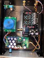
Here are my readings so far with inputs shorted to ground
Power Talema 15vac trafo then paired with VRDN psu for +15V/-15V
R6 - 865mv
R11 - 866mv
R106 - 779mv
R111 - 780mv
Voltage divided by 2.7ohm shown in ( )
R24 - 56mv (20.7mA)
R25 - 57mv (21.11mA)
R124 - 49mv (18.14mA)
R125 - 49mv (18.14mA)
R5 - 1.510v
R10 - 1.496v
R105 - 1.428v
R110 - 1.423v
Thanks
Power Talema 15vac trafo then paired with VRDN psu for +15V/-15V
R6 - 865mv
R11 - 866mv
R106 - 779mv
R111 - 780mv
Voltage divided by 2.7ohm shown in ( )
R24 - 56mv (20.7mA)
R25 - 57mv (21.11mA)
R124 - 49mv (18.14mA)
R125 - 49mv (18.14mA)
R5 - 1.510v
R10 - 1.496v
R105 - 1.428v
R110 - 1.423v
Thanks
Attachments

It should be OK. You may tune Q1- Q4 current by R9/109. Yes I use the plastic shaft extension for the pot. It avoids induced voltages when touching the knob and potential buzz. The effect is measurable and potentially audible.
Currently I am using R9/109 as 270R and what do you suggest based on my above readings to change this value to?It should be OK. You may tune Q1- Q4 current by R9/109.
R1,101 used 8k2 and R2,102 used 2k7 per the BOM suggestion.
Thanks
Gain linearity with respect to input voltage (+/-2V which corresponds to +/-10V output) and load resistance from 50 ohm to 1kohm

More on linearity topic in this thread.
More on linearity topic in this thread.

I can recommend using shoulder washers in an 8mm size if you prefer to use a metal extension rod.Thanks @Vunce I hope you receive the package soon.
I am searching on how to mount the alps pot to the front panel knob without making any contact with the chassis. I have the potentiometer shaft extension kit but that comes all in steel and 300mm long Aluminium rod. The coupler is also aluminium so in order to isolate the pot to the chassis I need to either use a non-metal coupler or a plastic rod.
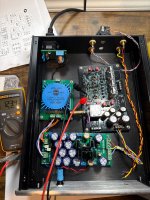
Thanks @PMA and yes I have the R8/108 as 100R. Now changed R9/109 to higher value but it’s dropping the voltage very less. So when I removed both the R9/109 keeping it open I get exact 1.226v across R5/105.And R8/R108 value? 100R?
I would increase R9/109 a bit to get about 1.25V across R5 and R10, but as I already said, it is not so critical. The recommended scenario is to start with R9/109 unconnected and to select them by measuring voltage drop.
Attachments
I would like to note that voltages measured across the resistors are not so critical. In my last sample, which uses stock LSK170C/LSJ74C, I measure this:

and both channel measure almost same distortion plots.
However, please keep in mind what I write in the manual:
This says that R8 must be selected according to JFET Idss range, to make it able to set appropriate idle current of the input JFET quadruple. This is important. As I have used parts with Idss > 16 mA, I had to use R8 = 200R in my last preamp sample.
and both channel measure almost same distortion plots.
However, please keep in mind what I write in the manual:
R8 value is 100R for Idss 5 – 9mA, 150R for Idss 9 – 12mA and 200R for Idss 12 - 20mA.
This says that R8 must be selected according to JFET Idss range, to make it able to set appropriate idle current of the input JFET quadruple. This is important. As I have used parts with Idss > 16 mA, I had to use R8 = 200R in my last preamp sample.
- Home
- Source & Line
- Analog Line Level
- Preamplifier Dispre 2 - JFET